Nissan Sentra B18 (2020-2025) Service Manual: Door Motor Circuit
Diagnosis Procedure
Diagnosis Procedure
Note:
If all of door motor DTCs are detected, check this circuit.
-
CHECK DOOR MOTOR POWER SUPPLY
-
-
Ignition switch ON.
-
Check voltage between intake door motor harness connector and ground.
+
-
Voltage
(Approx.)
Intake door motor
Connector
Terminal
M165
1
Ground
Battery voltage
-
Is the inspection result normal?
YES >>GO TO 2.
NO >>GO TO 7.
-
-
CHECK DOOR MOTOR GROUND CIRCUIT FOR OPEN
-
-
Ignition switch OFF.
-
Disconnect intake door motor connector.
-
Check continuity between intake door motor harness connector and ground.
Intake door motor
—
Continuity
Connector
Terminal
M165
2
Ground
Yes
-
Is the inspection result normal?
YES >>GO TO 3.
NO >>Repair harness or connector.
-
-
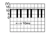
CHECK DOOR MOTOR LIN SIGNAL
-
-
Connect intake door motor connector.
-
Ignition switch ON.
-
Confirm output waveform between intake door motor harness connector and ground with oscilloscope.
+
-
Output waveform
Intake door motor
Connector
Terminal
M165
3
Ground
-
Is the inspection result normal?
YES >>GO TO 4.
NO >>GO TO 6.
-
-
CHECK DOOR MOTOR LIN SIGNAL CIRCUIT FOR OPEN
-
-
Ignition switch OFF.
-
Disconnect A/C auto amp. connector and intake door motor connector.
-
Check continuity between A/C auto amp. harness connector and intake door motor harness connector.
A/C auto amp.
Intake door motor
Continuity
Connector
Terminal
Connector
Terminal
M33
22
M165
3
Yes
-
Is the inspection result normal?
YES >>GO TO 5.
NO >>Repair harness or connector.
-
-
CHECK INTERMITTENT INCIDENT
-
Check intermittent incident. Refer to Intermittent Incident.
Inspection End.
-
-
CHECK DOOR MOTOR LIN SIGNAL CIRCUIT FOR SHORT
-
-
Ignition switch OFF.
-
Disconnect following connectors:
-
A/C auto amp.
-
Air mix door motor RH
-
Air mix door motor LH
-
Mode door motor
-
Intake door motor
-
-
Check continuity between A/C auto amp. harness connector and ground.
A/C auto amp.
—
Continuity
Connector
Terminal
M33
22
Ground
No
-
Is the inspection result normal?
YES >>Replace A/C auto amp. Refer to Removal and Installation.
NO >>Repair harness or connector.
-
-
CHECK DOOR MOTOR POWER SUPPLY CIRCUIT FOR OPEN
-
-
Ignition switch OFF.
-
Disconnect intake door motor connector and A/C auto amp. connector.
-
Check continuity between intake door motor harness connector and A/C auto amp. harness connector.
Intake door motor
A/C auto amp.
Continuity
Connector
Terminal
Connector
Terminal
M165
1
M33
1
Yes
-
Is the inspection result normal?
YES >>GO TO 8.
NO >>Repair harness or connector.
-
-
CHECK DOOR MOTOR POWER SUPPLY CIRCUIT FOR SHORT
-
-
Disconnect following connectors:
-
Air mix door motor RH
-
Air mix door motor LH
-
Mode door motor
-
-
Check continuity between A/C auto amp. harness connector and ground.
A/C auto amp.
—
Continuity
Connector
Terminal
M33
1
Ground
No
-
Is the inspection result normal?
YES >>Replace A/C auto amp. Refer to Removal and Installation.
NO >>Repair harness or connector.
-
Other materials:
LATCH (Lower Anchors and Tethers for CHildren) system
LATCH system lower anchor locations
Your Nissan Sentra is equipped with dedicated anchor points designed for use
with LATCH system–compatible child restraints. This system may also be referred
to as ISOFIX or ISOFIX-compatible. When using the LATCH system, a vehicle seat belt
is not req ...
Precautions for Refrigerant System Service
Precautions
For Refrigerant System Service
GENERAL REFRIGERANT PRECAUTION
Warning:
Do not breathe A/C refrigerant and oil vapor or
mist. Exposure may irritate eyes, nose and throat. Remove HFO-1234yf
(R-1234yf) from the A/C system, using certified s ...
Heated Seat Does Not Operate. Diagnosis Procedure
Diagnosis Procedure
Diagnosis Procedure
CHECK HEATED SEAT RELAY
Check heated seat relay.
Refer to Component Function Check (LH) or Component Function Check (RH).
Is the inspection result normal?
YES>>
GO TO
...