Nissan Sentra B18 (2020-2025) Service Manual: System
Headlamp System
System Description
System Description
SYSTEM DIAGRAM
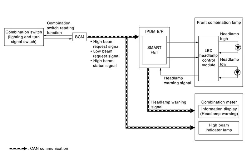
OUTLINE
The headlamp is controlled by the combination switch reading function and headlamp control function of the BCM, and the Smart FET control function of the IPDM E/R.
Signal transmission function list
|
Signal name |
Input |
Output |
Description |
|---|---|---|---|
|
Combination switch signal |
Combination switch (lighting and turn signal switch) |
BCM |
Transmits the combination switch signal to the BCM. |
|
Low beam request signal |
BCM |
IPDM E/R (CAN) |
Transmits the low beam request signal via CAN communication. |
|
High beam request signal |
BCM |
IPDM E/R (CAN) |
Transmits the high beam request signal via CAN communication. |
|
High beam status signal |
BCM |
Combination meter (CAN) |
Transmits the high beam status signal via CAN communication. |
HEADLAMP (LO) OPERATION
-
The BCM detects the combination switch (lighting and turn signal switch) condition with the combination switch reading function.
-
The BCM transmits the low beam request signal to the IPDM E/R via CAN communication according to the headlamp (LO) ON condition.
Headlamp (LO) ON condition (when any of the following conditions are satisfied):
-
Lighting switch 2ND
-
Lighting switch AUTO (only when the illumination judgement by auto light system is ON). Refer to System Description.
-
Lighting switch PASS
-
-
The IPDM E/R turns the integrated Smart FET ON according to the low beam request signal and supplies power supply to the LED headlamp control module.
-
The LED headlamp control module turns the headlamp (LO) ON according to the power supply from the IPDM E/R.
HEADLAMP (HI) OPERATION
-
The BCM transmits the high beam request signal to the IPDM E/R and high beam status signal to the combination meter via CAN communication according to the headlamp (HI) ON condition.
Headlamp (HI) ON condition (When any of the following conditions are satisfied):
-
Lighting switch HI with the lighting switch 2ND
-
Lighting switch HI with the lighting switch AUTO (only when the illumination judgement by auto light system is ON). Refer to System Description.
-
Lighting switch PASS
-
-
The IPDM E/R turns the integrated Smart FET ON according to the high beam request signal and supplies power supply to the LED headlamp control module.
-
The LED headlamp control module turns the headlamp (HI) ON according to the power supply from the IPDM E/R.
-
The combination meter turns the high beam indicator lamp ON according to the high beam status signal.
HEADLAMP WARNING OPERATION
The headlamp warning warns the driver that there is a malfunction in LED headlamp system. Refer to System Description.
LED HEADLAMP
-
Semiconductor device (light emitting diode: LED), which is illuminated when forward bias electric voltage is applied, is adopted as the source of light instead of halogen bulb or xenon bulb.
-
Comparing to halogen headlamp or xenon headlamp, LED headlamp is electrically power saving, durable, and is illumination in the similar color to the sunlight. Bright, natural, and eye-friendly visibility can be obtained.
Precautions for Trouble Diagnosis:
Representative malfunction examples are; “Light does not turn ON”, “Light blinks”, and “Brightness is inadequate.” Such malfunctions occasionally occur from a LED control module malfunction or lamp case malfunction. Specify the malfunctioning part through diagnosis.
CAUTION:
-
Never touch the harness, LED headlamp control module, the inside and metal part of lamp when turning the headlamp ON or operating the lighting switch to preventing electrical shock.
-
Never work with wet hands to prevent electrical shock.
-
Never perform LED headlamp control module circuit diagnosis with a circuit tester or equivalent.
-
Temporarily install the headlamps on the Nissan Sentra vehicle. Always connect power supply to the connector (vehicle side) when checking ON/OFF status.
-
Disconnect the battery negative terminal before disconnecting the lamp socket connector or the harness connector.
-
Check for blown (open) fusible link(s), open around connector, short and disconnection if the symptom is caused by electric error.
-
Always check for deformation of the headlamp housing and engagement of bulb cover. Otherwise, water may enter into headlamp causing damage of the headlamp housing or contact to LED headlamp control module connector. The normal operation may be inhibited when a short circuit to power supply is detected.

Turn the switch OFF once before turning ON, if the ON/OFF is inoperative.
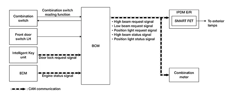
Auto Light System
System Description
System Description
SYSTEM DIAGRAM
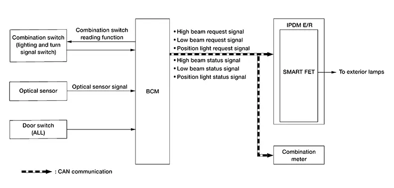
OUTLINE
-
The auto light system is controlled by each function of the BCM and IPDM E/R.
Control by BCM:
-
Combination switch reading function
-
Auto light function
-
Wiper linked auto lighting function
-
Delay timer function
Control by IPDM E/R:
-
Smart FET control function
-
-
The auto light system has the auto light function, wiper linked auto lighting function, and delay timer function.
-
The auto light function automatically turns ON/OFF the exterior lamps*, depending on the outside brightness.
-
The wiper linked auto lighting function automatically turns ON/OFF the exterior lamps* when the lighting switch is in the AUTO position, according to front wiper operation.
-
When the auto light system turns the headlamp ON with the ignition switch OFF, the delay timer function turns the headlamp OFF, depending on the Nissan Sentra vehicle condition with the auto light function after a certain period of time.
-
*: Headlamp (LO/HI), parking lamp, license plate lamp, side marker lamp and tail lamp.
Note:
-
Headlamp (HI) depend on the combination switch (lighting and turn signal switch) condition.
Signal transmission function list
|
Signal name |
Input |
Output |
Description |
|---|---|---|---|
|
Combination switch signal |
Combination switch (lighting and turn signal switch) |
BCM |
Transmits the combination switch signal to the BCM. |
|
Optical sensor signal |
Optical sensor |
BCM |
Transmits the optical sensor signal to the BCM. |
|
Door switch signal |
Door switch (ALL) |
BCM |
Transmits the door switch signal to the BCM. |
|
High beam request signal |
BCM |
IPDM E/R (CAN) |
Transmits the high beam request signal via CAN communication. |
|
Low beam request signal |
BCM |
IPDM E/R (CAN) |
Transmits the low beam request signal via CAN communication. |
|
Position light request signal |
BCM |
IPDM E/R (CAN) |
Transmits the position light request signal via CAN communication. |
|
High beam status signal |
BCM |
Combination meter (CAN) |
Transmits the high beam status signal via CAN communication. |
|
Low beam status signal |
BCM |
Combination meter (CAN) |
Transmits the low beam status signal via CAN communication. |
|
Position light status signal |
BCM |
Combination meter (CAN) |
Transmits the position light status signal via CAN communication. |
AUTO LIGHT FUNCTION
-
The BCM detects the combination switch (lighting and turn signal switch) condition with the combination switch reading function.
-
The BCM supplies voltage to the optical sensor when the ignition switch is ON.
-
The optical sensor converts outside brightness (lux) to voltage and transmits the optical sensor signal to the BCM.
-
When the ignition switch is ON, the BCM detects outside brightness from the optical sensor signal and judges the ON/OFF condition of each exterior lamp, depending on the outside brightness condition.
-
The BCM transmits each request signal to the IPDM E/R and each status signal to the combination meter via CAN communication, according to ON/OFF condition by the auto light function.
WIPER LINKED AUTO LIGHTING FUNCTION
The BCM turns each exterior lamp ON within 60 seconds detecting 4 operations of the front wiper while the lighting switch is in the AUTO position.
Note:
The BCM turns OFF the headlamps 3 seconds after the front wiper switch is turned OFF.
DELAY TIMER FUNCTION
The BCM turns the headlamp OFF depending on the Nissan Sentra vehicle condition with the auto light function.
-
Turns the headlamp OFF approx. 60 seconds after ignition switch OFF.
-
Headlamp (HI) depend on the combination switch (lighting and turn signal switch) condition.
-
When any position other than lighting switch AUTO is set, the auto light system function switches to the exterior lamp battery saver function.
Daytime Running Light System
System Description
System Description
SYSTEM DIAGRAM
OUTLINE
The daytime running light is controlled by the daytime running light control function and combination switch reading function of the BCM, and the Smart FET control function of the IPDM E/R.
Signal transmission function list
|
Signal name |
Input |
Output |
Description |
|---|---|---|---|
|
Combination switch signal |
Combination switch (lighting and turn signal switch) |
BCM |
Transmits the combination switch signal to the BCM. |
|
Engine status signal |
ECM |
BCM (CAN) |
Transmits the engine status signal via CAN communication. |
|
Parking brake switch signal |
Parking brake switch |
BCM (CAN) |
Inputs the parking brake switch signal and transmits it via CAN communication. |
|
Daytime running light request signal |
BCM |
IPDM E/R (CAN) |
Transmits the daytime running light request signal via CAN communication. |
DAYTIME RUNNING LIGHT OPERATION
-
The BCM detects the combination switch (lighting and turn signal switch) condition by the combination switch reading function.
-
The BCM detects the Nissan Sentra vehicle condition depending on the engine status signal (received from ECM via CAN communication).
-
The BCM transmits the daytime running light request signal to the IPDM E/R via CAN communication according to the daytime running light ON condition.
Daytime running light ON condition:
-
Engine running and any following conditions are satisfied:
-
Lighting switch OFF
-
Lighting switch AUTO (only when the illumination judgement by auto light system is OFF). Refer to System Description.
-
-
-
The IPDM E/R turns the integrated Smart FET ON, and turns the daytime running light ON according to the daytime running light request signal.
High Beam Assist System
System Description
System Description
SYSTEM DIAGRAM
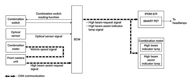
OUTLINE
-
The HBA (high beam assist) system is a system that can reduce the driver's switch operation load. The system automatically switches the headlamp to the low beam mode when a Nissan Sentra vehicle ahead or an oncoming vehicle appears, while driving the vehicle with the headlamps in high beam mode at night.
-
When the HBA system operation permission conditions are satisfied, the HBA indicator lamp in the combination meter turns ON and informs that the HBA system is in operation.
-
The HBA system is controlled by each function of the BCM, front camera unit and the IPDM E/R.
Control by BCM:
-
Combination switch reading function
-
Auto light function
-
HBA control function
-
Headlamp control function
Control by IPDM E/R:
-
Smart FET control function
Control by front camera unit:
-
HBA control function
-
Signal transmission function list
|
Signal name |
Input |
Output |
Description |
|---|---|---|---|
|
Combination switch signal |
Combination switch |
BCM |
Transmits the combination switch signal to the BCM. |
|
Optical sensor signal |
Optical sensor |
BCM |
Transmits the optical sensor signal to the BCM. |
|
Nissan Sentra Vehicle speed signal |
Combination meter |
Front camera unit (CAN) |
Transmits the Nissan Sentra vehicle speed signal via CAN communication. |
|
High beam assist request signal |
Front camera unit |
BCM (CAN) |
Transmits the high beam assist request signal via CAN communication. |
|
High beam request signal |
BCM |
IPDM E/R (CAN) |
Transmits the high beam request signal via CAN communication. |
|
High beam assist indicator lamp signal |
BCM |
Combination meter (CAN) |
Transmits the high beam assist indicator lamp signal via CAN communication. |
OPERATION DESCRIPTION
-
The BCM detects the combination switch (lighting and turn signal switch) condition with the combination switch reading function.
-
The BCM transmits the HBA indicator lamp signal to the combination meter via CAN communication, when the HBA system operation permission conditions are satisfied.
HBA system operation permission conditions:
-
Lighting switch HI with the lighting switch AUTO and ignition switch ON (only when the illuminating judgment by auto light function is ON). For details, refer to System Description.
-
-
The combination meter turns the HBA indicator lamp ON according to the HBA indicator lamp signal.
-
The Front camera unit detects the Nissan Sentra vehicle status and ambient status that are required for HBA control with the following signals:
-
Nissan Sentra Vehicle speed signal (received from combination meter via CAN communication)
-
Ambient light signal (detected from front camera unit)
-
Image sensor signal (detected from front camera unit)
-
-
The front camera unit judges the current recommended beam according to the Nissan Sentra vehicle status and ambient condition, and transmits the HBA request signal (headlamp HI operation / headlamp LO operation) to the BCM via CAN communication.
-
The BCM switches the headlamp LO operation / headlamp HI operation according to the HBA request signal, while the HBA system operation permission conditions are satisfied. For headlamp operation; Refer to System Description.
RECOMMENDED BEAM JUDGMENT BY FRONT CAMERA UNIT
Headlamp HI Operation Request
The front camera unit requests headlamp HI operation to the BCM when all of following conditions are satisfied:
-
Detects the Nissan Sentra vehicle speed is approx. 19 MPH (30 km/h) or more.
-
Recognizes the ambient condition is dark.
-
Recognizes there is no oncoming Nissan Sentra vehicle or no vehicle ahead in front of the vehicle.
Headlamp LO Operation Request
Front camera unit requests the headlamp LO operation to the BCM when either of following conditions is satisfied:
-
Detects the Nissan Sentra vehicle speed is approx. 12 MPH (20 km/h) or less.
-
Recognizes the ambient condition is bright.
-
Recognizes there is oncoming Nissan Sentra vehicle or vehicle ahead in front of the vehicle.
Turn Signal and Hazard Warning Lamp System
System Description
System Description
SYSTEM DIAGRAM
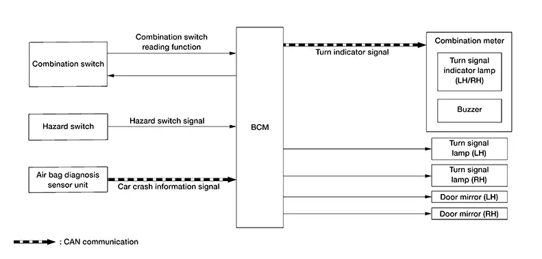
OUTLINE
Turn signal lamp and hazard warning lamp is controlled by the combination switch reading function and the flasher control function of the BCM.
Signal transmission function list
|
Signal name |
Input |
Output |
Description |
|---|---|---|---|
|
Combination switch signal |
Combination switch |
BCM |
Transmits the combination switch signal to the BCM. |
|
Hazard switch signal |
Hazard switch |
BCM |
Transmits the hazard switch signal to the BCM. |
|
Car crash information signal |
Air bag diagnosis sensor unit |
BCM (CAN) |
Transmits the car crash information signal via CAN communication. |
|
Turn indicator signal |
BCM |
Combination meter (CAN) |
Transmits the turn indicator signal via CAN communication. |
TURN SIGNAL LAMP OPERATION
-
The BCM detects the combination switch (lighting and turn signal switch) condition by the combination switch reading function.
-
The BCM supplies voltage to the left or right turn signal lamp circuits when the ignition switch is ON and the turn signal switch is in the left or right position. The BCM blinks the turn signal lamp.
HAZARD WARNING LAMP OPERATION
The BCM supplies voltage to both turn signal lamp circuits when the hazard switch is ON. the BCM blinks the hazard warning lamp.
TURN SIGNAL INDICATOR LAMP AND TURN SIGNAL SOUND OPERATION
-
The BCM transmits the turn indicator signal to the combination meter via CAN communication while the turn signal lamp and the hazard warning lamp are operating.
-
The combination meter outputs the turn signal sound with its integrated buzzer while blinking the turn signal indicator lamp according to the turn indicator signal.
3-TIME FLASHER FUNCTION
-
By a short touch of the turn signal lever, the BCM blinks the turn signal lamps 3 times in the selected direction.
-
The BCM cancels the operation with a short touch of the turn signal lever in the reverse direction during the 3-time flasher function operation.
HIGH FLASHER OPERATION
-
The BCM detects the turn signal lamp circuit status from the current value.
-
The BCM increases the turn signal lamp blinking speed if the bulb or harness open is detected with the turn signal lamp operating.
Note:
The blinking speed is normal while operating the hazard warning lamp.
AUTO HAZARD FUNCTION
-
The air bag diagnosis sensor unit transmits a car crash information signal to the BCM via CAN communication, when the air bag diagnosis sensor unit detects strong impact to the Nissan Sentra vehicle body while ignition switch is ON.
-
When a car crash information signal from the air bag diagnosis sensor unit is detected, the BCM supplies voltage to each turn signal lamp system and the hazard lamp blinks.
Parking, License Plate, Side Marker and Tail Lamp System
System Description
System Description
SYSTEM DIAGRAM
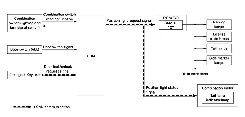
OUTLINE
The parking, license plate, side marker and tail lamps are controlled by the combination switch reading function, the parking, license plate, side marker and tail lamp control function of the BCM, and the Smart FET control function of the IPDM E/R.
Signal transmission function list
|
Signal name |
Input |
Output |
Description |
|---|---|---|---|
|
Combination switch signal |
Combination switch (lighting and turn signal switch) |
BCM |
Transmits the combination switch signal to the BCM. |
|
Door switch signal |
Door switch (ALL) |
BCM |
Transmits the door switch signal to the BCM. |
|
Door lock/unlock request signal |
Intelligent Key unit |
BCM (CAN) |
Transmits the door lock/unlock request signal via CAN communication. |
|
Position light request signal |
BCM |
IPDM E/R (CAN) |
Transmits the position light request signal via CAN communication. |
|
Position light status signal |
BCM |
Combination meter (CAN) |
Transmits position light status signal via CAN communication. |
PARKING, LICENSE PLATE, SIDE MARKER AND TAIL LAMP OPERATION
-
The BCM detects the combination switch (lighting and turn signal switch) condition by the combination switch reading function.
-
The BCM transmits the position light request signal to the IPDM E/R and position light status signal to the combination meter via CAN communication according to the parking, license plate, side marker and tail lamp ON condition.
Parking, license plate, side marker and tail lamp ON condition (when any of the following conditions are satisfied):
-
Lighting switch 1ST
-
Lighting switch 2ND
-
Lighting switch AUTO (only when the illumination judgement by auto light system is ON). Refer to System Description.
-
-
The IPDM E/R turns the integrated Smart FET ON and turns the parking, license plate, side marker and tail lamp ON according to the position light request signal.
-
The combination meter turns the position light indicator lamp ON according to the position light status signal.
The parking lamp and daytime running light use a common light source. When the parking, license plate, side marker and tail lamps are turned ON while daytime running lights are ON, the parking lamp/daytime running light is dimmed.
SIGNATURE LIGHT FUNCTION
Description
The signature light function is a function that turns ON the parking lamp, license plate lamp, side marker lamp and tail lamp for a set period of time when the doors are locked or unlocked from outside the Nissan Sentra vehicle.
Operation Description
The BCM transmits the position light request signal to the IPDM E/R and position light status signal to the combination meter via CAN communication according to the signature light function ON condition.
Signature light function ON condition (operation when doors are unlocked):
-
When all of the following conditions are satisfied, the signature light function operates when door unlock operation is performed from outside the Nissan Sentra vehicle (Intelligent Key, door request switch, etc.):
-
Ignition switch: OFF
-
Door open/close status: All door close
-
Door lock status: All door lock
-
-
When any of the following conditions are satisfied while the signature light function is operating, the signature light function stops:
-
Ignition switch: ON
-
Door lock status: All door lock (this only occurs when door lock operation is performed using the door lock and unlock switch, etc. When door lock operation is performed with the Intelligent Key or door request switch, the system changes to operation when doors are locked).
-
Since signature light function ON, approx. 30 seconds are passed.
-
Signature light function ON condition (operation when doors are locked)
Note:
ON/OFF of signature light function by lock operation is by the setting “Light Off Delay” of the combination meter.
-
When all of the following conditions are satisfied, the signature light function operates when door lock operation is performed from outside the Nissan Sentra vehicle (Intelligent Key or door request switch, etc.):
-
Ignition switch: OFF
-
Door open/close status: All door close
-
-
When any of the following conditions are satisfied while the signature light function is operating, the signature light function stops:
-
Ignition switch: ON
-
Door lock status: Any door unlock or all door unlock (this only occurs when door unlock operation is performed using the door lock and unlock switch etc. When door unlock operation is performed with the Intelligent Key or door request switch, the system changes to operation when doors are unlocked).
-
Since signature light function ON, approx. 10 seconds are passed.
-
Stop Lamp System
System Description
System Description
SYSTEM DIAGRAM
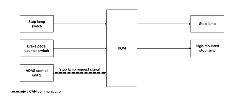
OUTLINE
The stop lamp and high-mounted stop lamp are controlled by the stop lamp switch reading function, the stop lamp and high-mounted stop lamp control function of the BCM, and the AEB (automatic emergency braking) function of the ADAS control unit 2.
Signal transmission function list
|
Signal name |
Input |
Output |
Description |
|---|---|---|---|
|
Stop lamp switch signal |
Stop lamp switch |
BCM |
Transmits the stop lamp switch signal to the BCM. |
|
Brake pedal position switch signal |
Brake pedal position switch |
BCM |
Transmits the brake pedal position switch signal to the BCM. |
|
Stop lamp request signal |
ADAS control unit 2 |
BCM (CAN) |
Transmits the stop lamp request signal via CAN communication. |
STOP LAMP AND HIGH-MOUNTED STOP LAMP OPERATION
-
The BCM detects the brake pedal position status from stop lamp switch/brake pedal position switch.
-
The BCM supplies voltage to stop lamp and high-mounted stop lamp according to the stop lamp and high-mounted stop lamp ON condition.
Stop lamp and high-mounted stop lamp ON condition:
-
Brake pedal is depressed
-
AUTOMATIC EMERGENCY BRAKING FUNCTION
-
When the AEB system operates, the ADAS control unit 2 transmits the stop lamp request signal to the BCM via CAN communication. For details about the AEB refer to System Description.
-
When the BCM receives the stop lamp request signal from the ADAS control unit 2, it supplies power to the stop lamp and high-mounted stop lamp systems, turning ON the stop lamp and high-mounted stop lamp.
Back-Up Lamp System
System Description (with Cvt)
System Description (With CVT)
SYSTEM DIAGRAM
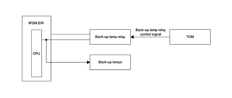
OUTLINE
The back-up lamps are controlled by the TCM.
BACK-UP LAMP OPERATION
-
The TCM detects the shift selector position status from the transmission range switch.
-
The TCM controls the back-up lamp relay based on the shift selector position.
-
The TCM turns the back-up lamp relay ON when the back-up lamp ON conditions are satisfied.
Back-up lamp ON conditions:
-
Ignition switch ON
-
Shift selector position R
-
System Description (with M/t)
System Description (With M/T)
SYSTEM DIAGRAM
OUTLINE
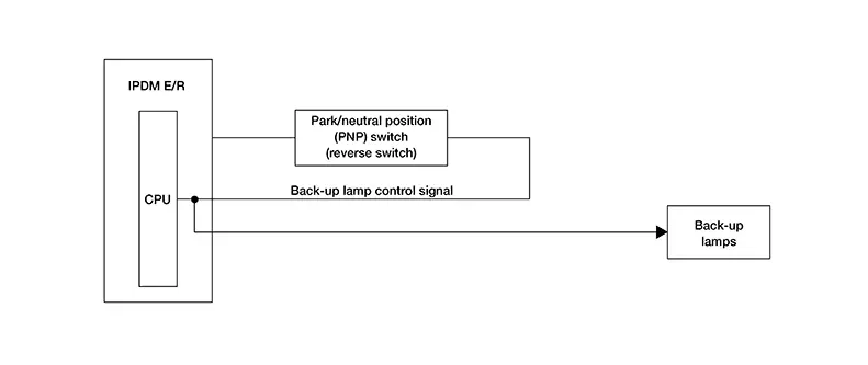
The back-up lamps are controlled by the park/neutral position (PNP) switch (reverse switch).
Signal transmission function list
|
Signal name |
Input |
Output |
Description |
|---|---|---|---|
|
Back-up lamp control signal |
Park/neutral position (PNP) switch (reverse switch) |
IPDM E/R |
Transmits the back-up lamp control signal to the IPDM E/R. |
BACK-UP LAMP OPERATION
-
The IPDM E/R detects the shift selector position status from the park/neutral position (PNP) switch (reverse switch).
-
The park/neutral position (PNP) switch (reverse switch) turns the back-up lamps ON when the back-up lamp ON conditions are satisfied.
Back-up lamp ON conditions:
-
Ignition switch ON
-
Shift selector position R
-
Exterior Lamp Battery Saver System
System Description
System Description
SYSTEM DIAGRAM
OUTLINE
-
The exterior lamp battery saver system is controlled by the combination switch reading function, the exterior lamp battery saver function of the BCM, and the Smart FET control function of the IPDM E/R.
-
The BCM turns the exterior lamp* OFF, according to the Nissan Sentra vehicle status when ignition switch is placed OFF while the exterior lamp is ON, for preventing battery discharge.
*: Headlamp (LO/HI), parking lamp, license plate lamp, side marker lamp and tail lamp
Signal transmission function list
|
Signal name |
Input |
Output |
Description |
|---|---|---|---|
|
Combination switch signal |
Combination switch |
BCM |
Transmits the combination switch signal to the BCM. |
|
Door switch signal |
Front door switch LH |
BCM |
Transmits the door switch signal to the BCM. |
|
Door lock request signal |
Intelligent Key unit |
BCM (CAN) |
Transmits the door lock request signal via CAN communication. |
|
Engine status signal |
ECM |
BCM (CAN) |
Transmits the engine status signal via CAN communication. |
|
High beam request signal |
BCM |
IPDM E/R (CAN) |
Transmits the high beam request signal via CAN communication. |
|
Low beam request signal |
BCM |
IPDM E/R (CAN) |
Transmits the low beam request signal via CAN communication. |
|
Position light request signal |
BCM |
IPDM E/R (CAN) |
Transmits the position light request signal via CAN communication. |
|
High beam status signal |
BCM |
Combination meter (CAN) |
Transmits the high beam status signal via CAN communication. |
|
Low beam status signal |
BCM |
Combination meter (CAN) |
Transmits the low beam status signal via CAN communication. |
|
Position light status signal |
BCM |
Combination meter (CAN) |
Transmits the position light status signal via CAN communication. |
EXTERIOR LAMP BATTERY SAVER ACTIVATION
-
The BCM turns the exterior lamps OFF (battery saver is activated) when all of the following conditions are satisfied:
-
Exterior lamp: ON
-
Engine status: Running => Stop (ignition switch is placed OFF)
-
Front door LH is turned from CLOSED to OPEN [front door switch LH OFF to ON] or door lock operation (operate with Intelligent Key, door request switch, etc.)
-
-
When in any of following conditions (after the exterior lamp battery saver is activated), the exterior lamps can be turned ON:
-
Ignition switch is placed from OFF => other than OFF
-
Lighting switch is changed
-
Light Reminder Warning (information Display)
System Description
System Description
SYSTEM DIAGRAM
OUTLINE
When the driver is exiting the Nissan Sentra vehicle while the engine status is other than running and the lamps are ON, the light reminder warning (information display) displays a warning in the information display to alert the driver.
Signal transmission function list
|
Signal name |
Input |
Output |
Description |
|---|---|---|---|
|
Combination switch signal |
Combination switch |
BCM |
Transmits the combination switch signal to the BCM. |
|
Engine status signal |
ECM |
BCM (CAN) |
Transmits the engine status signal via CAN communication. |
|
Door switch signal |
Front door switch LH |
BCM |
Transmits the door switch signal to the BCM. |
|
Light reminder warning signal |
BCM |
Combination meter (CAN) |
Transmits the light reminder warning via CAN communication. |
LIGHT REMINDER WARNING OPERATION
-
The BCM reads status of the combination switch (lighting and turn signal switch).
-
The BCM detects Nissan Sentra vehicle condition depending on the engine status signal (received from ECM via CAN communication).
-
The BCM judges light reminder warning (information display) by lighting switch signal, front door switch LH signal, and engine status signal. The BCM transmits the light reminder warning signal to the combination meter via CAN communication.
-
When the combination meter receives the light reminder warning signal, light reminder warning pop-up screen appears in the information display.
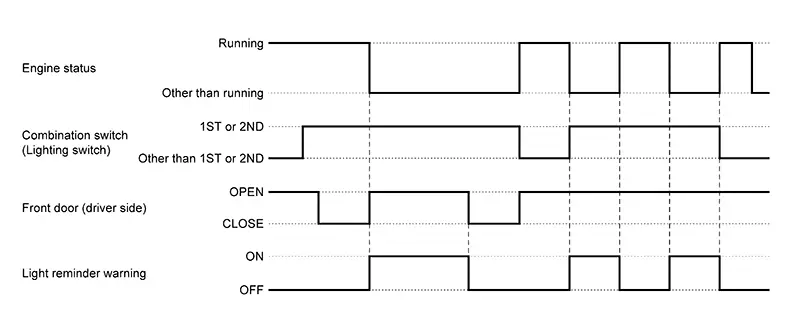
WARNING/INDICATOR OPERATING CONDITION
When all of the following conditions are satisfied:
-
Engine status is other than running
-
Lighting switch 1ST or 2ND
-
Front door LH side OPEN [front door switch LH ON]
|
Symbol |
Message |
|---|---|
 |
Reminder Turn OFF Headlights |
|
Symbol |
Message |
|---|---|
 |
Reminder Turn OFF Headlights |
WARNING/INDICATOR CANCEL CONDITION
When any of the following conditions are satisfied:
-
Engine status is running
-
Lighting switch other than 1ST or 2ND
-
Front door LH CLOSED [front door switch LH OFF]
TIMING CHART
Headlamp Warning
System Description
System Description
SYSTEM DIAGRAM
OUTLINE
The headlamp warning warns the driver that there is a malfunction in LED headlamp system.
Signal transmission function list
|
Signal name |
Input |
Output |
Description |
|---|---|---|---|
|
Low beam request signal |
BCM |
IPDM E/R (CAN) |
Transmits the low beam request signal to the BCM. |
|
Headlamp warning signal |
LED headlamp control module |
Combination meter (CAN) |
Inputs the headlamp warning signal and transmits it via CAN communication. |
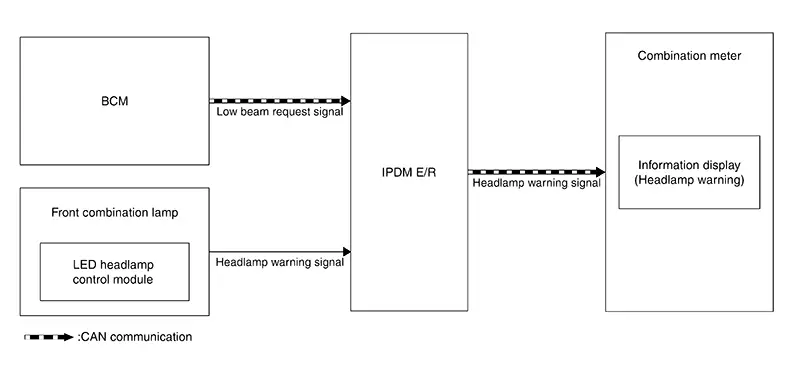
SIGNAL PATH
-
The BCM transmits the low beam request signal to the IPDM E/R via CAN communication with headlamp (LO) ON judgement.
-
When the LED headlamp control module detects a malfunction of the headlamp (LO) circuit, the headlamp warning signal is output to the IPDM E/R.
-
When the IPDM E/R receives the low beam request signal and the headlamp warning signal is input, it transmits the headlamp warning signal via CAN communication to the combination meter.
-
When the ignition switch is ON and the combination meter receives the headlamp warning signal, the combination meter displays the headlamp warning on the information display.
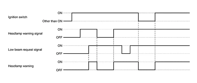
WARNING/INDICATOR OPERATING CONDITION
When all of the following conditions are satisfied:
-
Ignition switch ON
-
Headlamp warning signal via CAN communication is ON (IPDM E/R receives the low beam request signal and inputs the headlamp warning signal).
Note:Symbol
Message
—
Headlight
System Error
See Owner′s Manual
When the headlamp warning signal is received, the most likely cause is a malfunction of the following:
-
Headlamp (LO) power supply/ground circuit
-
Headlamp warning signal circuit
-
Front combination lamp
-
LED [headlamp (LO)]
-
LED headlamp control module
-
Harness
-
-
WARNING/INDICATOR CANCEL CONDITION
When any of the following conditions are satisfied:
-
Ignition switch other than ON
-
Headlamp warning signal via CAN communication is OFF (IPDM E/R receives the low beam request signal and does not input the headlamp warning signal).
TIMING CHART
Other materials:
Consult Checking System
Description
Description
Note:
This vehicle is diagnosed using the CONSULT-III
plus.
When CONSULT is connected with a data link connector equipped on the
Nissan Sentra vehicle side, it will
communicate with the control unit equipped in the vehicle and then
...
C1711-7b Low Tire Pressure Fl
Dtc Description
DTC Description
Note:
The Signal Tech II Tool [– (NI-50190)] can be used
to perform the following functions: Refer to the Signal Tech II User
Guide for additional information.
Activate and display TPMS sensor IDs
Display tire pressure rep ...
P0171 Fuel Injection System Function
Dtc Description
DTC Description
With the Air/Fuel Mixture Ratio Self-Learning Control, the actual
mixture ratio can be brought closely to the theoretical mixture ratio based on
the mixture ratio feedback signal from A/F sensor 1. The ECM calculatesthe
necessary compensation to corre ...