Nissan Sentra B18 (2020-2025) Service Manual: Component Parts
Exterior Lighting System
Component Parts Location
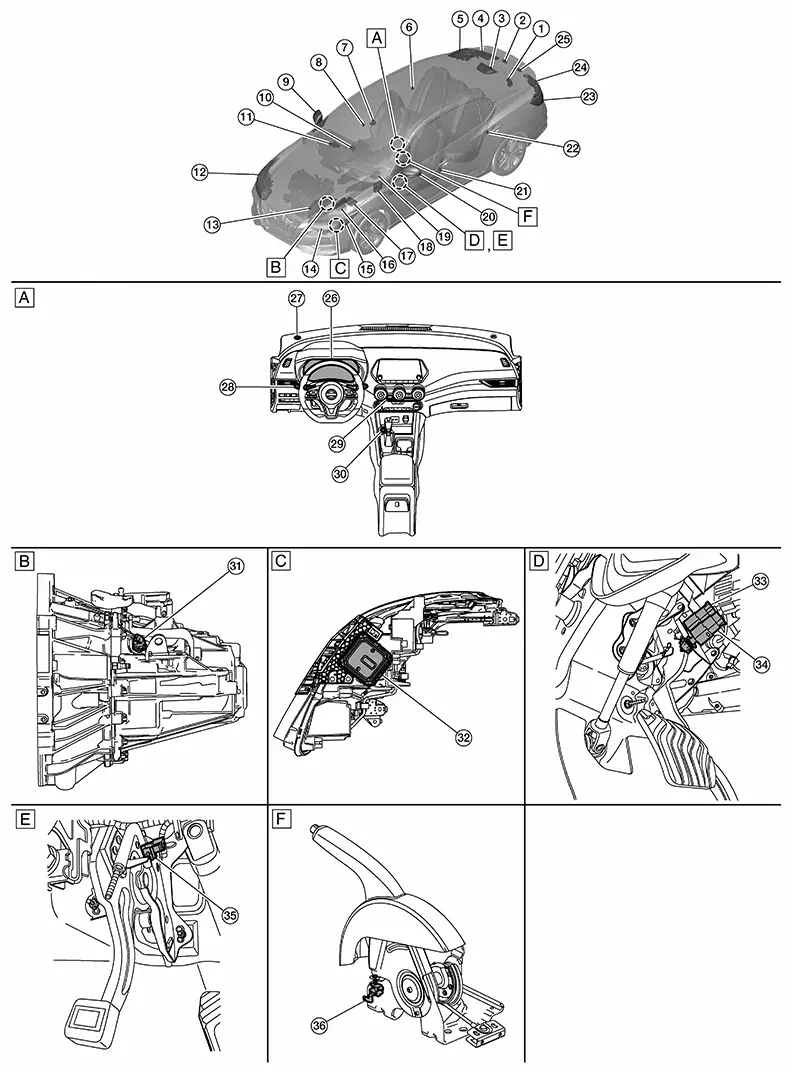
Component Parts Location
|
A. |
View of instrument panel |
B. |
M/T transmission (view with M/T transmission removed) |
C. |
Front combination lamp LH [RH similar (view with font combination lamp removed)] |
|
D. |
Underneath LH side of instrument panel |
E. |
Underneath LH side of instrument panel (with CVT) |
F. |
Underneath center console (view with parking brake lever removed) (with M/T) |
|
No. |
Component |
Function |
|
|---|---|---|---|
|
1. |
Trunk lid opener assembly (ajar switch) |
Transmits the ajar switch signal to the BCM. Refer to Trunk Lid Opener Assembly for detailed component location. |
|
|
2. |
License plate lamp RH |
Refer to Bulb Specifications. |
|
|
3. |
High-mounted stop lamp |
Refer to Bulb Specifications. |
|
|
4. |
Rear combination lamp RH (trunk lid side) |
Tail lamp |
Refer to Bulb Specifications. |
|
Back-up lamp |
|||
|
5. |
Rear combination lamp RH (body side) |
Tail lamp |
Refer to Bulb Specifications. |
|
Stop lamp |
|||
|
Rear turn signal lamp |
|||
|
6. |
Rear door switch RH |
Transmits the door switch signal to the BCM. Refer to Rear Door Switch for detailed component location. |
|
|
7. |
Front camera unit |
Detects a Nissan Sentra vehicle ahead or when an oncoming vehicle appears to operate the HBA (high beam assist) system. Refer to Front Camera Unit for detailed component location. |
|
|
8. |
Front door switch RH |
Transmits the door switch signal to the BCM. Refer to Front Door Switch for detailed component location. |
|
|
9. |
Door mirror RH |
[Side turn signal lamp (if so equipped)] |
Refer to Bulb Specifications. |
|
10. |
ADAS (Advanced Driver Assistance System) control unit 2 |
Transmits the stop lamp request signal to the BCM via CAN communication. Refer to ADAS Control Unit 2 for detailed component location. |
|
|
11. |
Intelligent Key unit |
Transmits the door lock/unlock request signal to the BCM via CAN communication. Refer to Intelligent Key Unit for detailed component location. |
|
|
12. |
Front combination lamp RH |
Headlamp (high) |
Refer to Bulb Specifications. |
|
Headlamp (low) |
|||
|
Daytime running light |
|||
|
Front turn signal lamp |
|||
|
Parking lamp |
|||
|
Front side marker lamp |
|||
|
13. |
CVT unit (if so equipped) |
Transmission range switch |
Transmits the transmission range switch signal to the TCM. Refer to Transmission range switch for detailed component location. |
|
14. |
TCM [Transmission Control Module (with CVT)] |
Detects that the shift selector is in the "R" position and turns the back-up lamp relay ON/OFF. Refer to TCM for detailed component location. |
|
|
15. |
Front combination lamp LH |
Headlamp (high) |
Refer to Bulb Specifications. |
|
Headlamp (low) |
|||
|
Daytime running light |
|||
|
Front turn signal lamp |
|||
|
Parking lamp |
|||
|
Front side marker lamp |
|||
|
16. |
ECM (Engine Control Module) |
Transmits the engine status signal to the BCM via CAN communication. Refer to ECM for detailed component location. |
|
|
17. |
IPDM E/R (Intelligent Power Distribution Module Engine Room) |
Supplies voltage to the loads according to the request from the BCM via CAN communication. Refer to System Description. |
|
|
18. |
BCM (Body Control Module) |
Refer to System Description. |
|
|
19. |
Air bag diagnosis sensor unit |
Transmits car crash information signal to the BCM via CAN communication. Refer to Air Bag Diagnosis Sensor Unit for detailed component location. |
|
|
20. |
Door mirror LH |
[Side turn signal lamp (if so equipped)] |
Refer to Bulb Specifications. |
|
21. |
Front door switch LH |
Transmits the door switch signal to the BCM. Refer to Front Door Switch for detailed component location. |
|
|
22. |
Rear door switch LH |
Transmits the door switch signal to the BCM. Refer to Rear Door Switch for detailed component location. |
|
|
23. |
Rear combination lamp LH (body side) |
Tail lamp |
Refer to Bulb Specifications. |
|
Stop lamp |
|||
|
Rear turn signal lamp |
|||
|
24. |
Rear combination lamp LH (trunk lid side) |
Tail lamp |
Refer to Bulb Specifications. |
|
Back-up lamp |
|||
|
25. |
License plate lamp LH |
Refer to Bulb Specifications. |
|
|
26. |
Combination meter |
Refer to Combination Meter for detailed component location. |
|
|
27. |
Optical sensor |
Refer to Optical Sensor. |
|
|
28. |
Combination switch (lighting and turn signal switch) |
Transmits the status of the combination switch (lighting and turn signal switch) to the BCM. Refer to System Description. |
|
|
29. |
Hazard switch |
Refer to Hazard Switch. |
|
|
30. |
Push-button ignition switch |
Refer to Push-Button Ignition Switch for detailed component location. |
|
|
31. |
Park/neutral position (PNP) switch (reverse switch) (with M/T) |
Detects that the shift selector is in the "R" position and turns the back-up lamps ON/OFF. |
|
|
32. |
LED headlamp control module |
Refer to LED Headlamp Control Module. |
|
|
33. |
Brake pedal position switch |
Refer to Brake Pedal Position Switch. |
|
|
34. |
Stop lamp switch |
Refer to Stop Lamp Switch. |
|
|
35. |
Parking brake switch (with CVT) |
Transmits the parking brake switch signal to the combination meter. |
|
|
36. |
Parking brake switch (with M/T) |
Transmits the parking brake switch signal to the combination meter. |
|
Optical Sensor
Optical Sensor
-
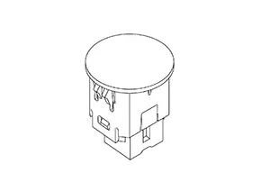
Optical sensor is installed in the LH side of instrument panel.
-
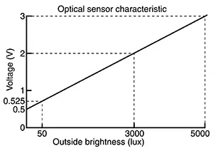
Optical sensor converts the outside brightness (lux) to voltage and transmits the optical sensor signal to the BCM.
-
The optical sensor outputs voltage signals to the BCM according to the brightness of the ambient light. This sensor increases the voltage output according to increases in the brightness of the ambient light.
Stop Lamp Switch
Stop Lamp Switch
-
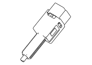
The stop lamp switch is installed on the brake pedal assembly.
-
The BCM detects the ON/OFF status of the stop lamp switch and illuminates the stop lamps.
Brake Pedal Position Switch
Brake Pedal Position Switch
-
The brake pedal position switch is installed on the brake pedal assembly.
-
The BCM detects the ON/OFF status of the brake pedal position switch and illuminates the stop lamps.
Hazard Switch
Hazard Switch
-
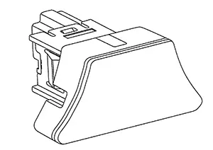
The hazard switch is installed in the center of the instrument panel.
-
Outputs the ON/OFF status of the hazard switch to the BCM, flashing the hazard warning lamps.
Led Headlamp Control Module
LED Headlamp Control Module
-
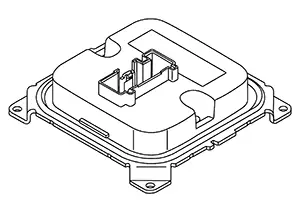
The LED headlamp control module is mounted to the bottom of the front combination lamp LH and front combination lamp RH.
-
When power is supplied from the IPDM E/R, the LED headlamp control module internally calculates the supplied power. The calculated power is distributed to multiple LEDs that consist of circuit boards and other components, illuminating the LED headlamps.
-
When a malfunction is detected in the headlamp (LO) circuit, the LED headlamp control module outputs a headlamp warning signal to the IPDM E/R to inform the driver of the malfunction.
Other materials:
Door Lock Function
System Diagram
System Diagram
System Description
System Description
Only when pressing the door request switch it is
possible to lock and unlock the door by carrying the Intelligent
Key.
INPUT SIGNAL AND OUTPUT SIGNAL
...
Body Sealing
Description
Description
The following figure shows the areas which are
sealed at the factory. Sealant which has been applied to these
areas should be smooth and free from cuts or gaps. Care should be
taken not to apply an excess amount of sealant and not to allow
other unaffecte ...
Component Parts
Meter System
Component Parts Location
Component Parts
Location
MODELS WITH CVT
A.
View of engine assembly removed
...