Nissan Sentra B18 (2020-2025) Service Manual: P0171 Fuel Injection System Function
Dtc Description
DTC Description
With the Air/Fuel Mixture Ratio Self-Learning Control, the actual mixture ratio can be brought closely to the theoretical mixture ratio based on the mixture ratio feedback signal from A/F sensor 1. The ECM calculatesthe necessary compensation to correct the offset between the actual and the theoretical ratios.
In case the amount of the compensation value is extremely large (the actual mixture ratio is too lean), the ECM judges the condition as the fuel injection system malfunction and illuminates the MIL (2 trip detection logic).
|
Sensor |
Input signal to ECM |
ECM function |
Actuator |
|---|---|---|---|
|
A/F sensor 1 |
Density of oxygen in exhaust gas (Mixture ratio feedback signal) |
Fuel injection control |
Fuel injector |
DTC DETECTION LOGIC
|
DTC |
CONSULT screen terms (Trouble diagnosis content) |
DTC detection condition |
|
|
P0171 |
FUEL SYS-LEAN-B1 (System too lean bank 1) |
Diagnosis condition |
ŌĆö |
|
Signal (terminal) |
ŌĆö |
||
|
Threshold |
|
||
|
Diagnosis delay time |
ŌĆö |
||
POSSIBLE CAUSE
-
Intake air leakage
-
A/F sensor 1
-
Fuel injector
-
Exhaust gas leakage
-
Incorrect fuel pressure
-
Lack of fuel
-
Mass air flow sensor
-
Incorrect PCV hose connection
FAIL-SAFE
Engine Control System
|
Engine operating condition in fail-safe mode |
||
|---|---|---|
|
Fail safe mode |
Nissan Sentra Vehicle behavior |
|
|
Traveling control mode |
Accelerator angle variation control |
ECM controls the accelerator pedal depression speed to make it slower than actual speed. This causes a drop in accelerating performance and encourages the driver to repair malfunction. Note:
ECM does not control the accelerator pedal releasing speed. |
|
Combustion control mode |
Stratified charge combustion control at starting |
No stratified charge combustion at starting (cold start). |
|
Idle speed control |
Stops feedback control of idle speed and controls with specified speed. |
|
|
Recovery speed control at decelerating |
Stops recovery speed control by the fuel cut at decelerating and controls with specified speed. |
|
|
Idle neutral control |
Stops idle neutral control. |
|
Idle Start/Stop System
When a DTC is detected, the start/stop indicator lamp blinks slowly and the idle start/stop system operation is prohibited.
When ECM detects error while operating the idle start/stop system, ECM restarts the engine.
Confirmation Procedure
Confirmation Procedure
-
PRECONDITIONING
If DTC Confirmation Procedure has been previously conducted, always perform the following procedure before conducting the next test.
>>GO TO 2.
-
PERFORM DTC CONFIRMATION PROCEDURE-1
-
Clear the mixture ratio self-learning value. Refer to DTC Description.
-
Start engine.
Is it difficult to start engine?
YES >>GO TO 3.
NO >>GO TO 4.
-
-
RESTART ENGINE
If it is difficult to start engine, the fuel injection system has a malfunction, too.
Crank engine while depressing accelerator pedal.
Note:
When depressing accelerator pedal three fourths (3/4) or more, the control system does not start the engine. Do not depress accelerator pedal too much.
Does engine start?
YES >>Proceed to DTC Diagnosis Procedure.
NO >>Check exhaust and intake air leakage visually.
-
PERFORM DTC CONFIRMATION PROCEDURE-2
-
Keep engine idle for at least 10 minutes.
-
Check 1st trip DTC.
Is 1st trip DTC detected?
YES >>Proceed to DTC Diagnosis Procedure.
NO >>GO TO 5.
-
-
PERFORM DTC CONFIRMATION PROCEDURE-3
-
Turn ignition switch OFF and wait at least 10 seconds.
-
Start engine and Maintain the following conditions for at least 10 consecutive minutes. Hold the accelerator pedal as steady as possible.
Nissan Sentra Vehicle speed
50 ŌĆō 100 km/h (31 ŌĆō 62 MPH)
CAUTION:
Always drive Nissan Sentra vehicle at a safe speed.
-
Check 1st trip DTC.
Is 1st trip DTC detected?
YES >>Proceed to DTC Diagnosis Procedure.
NO-1 >>To check malfunction symptom before repair: Refer to Intermittent Incident.
NO-2 >>Confirmation after repair: INSPECTION END
-
Dtc Diagnosis Procedure
DTC Diagnosis Procedure
-
CHECK EXHAUST GAS LEAKAGE
-
Start engine and run it at idle.
-
Listen for an exhaust gas leakage before three way catalyst (manifold).
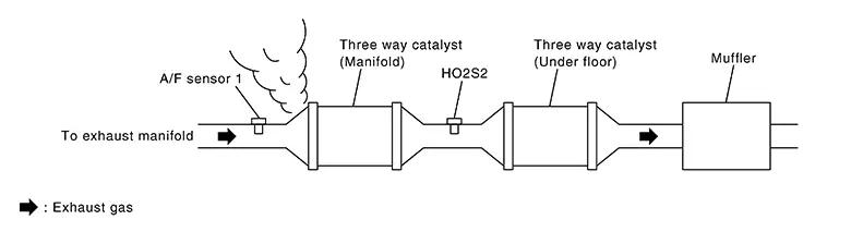
Is exhaust gas leakage detected?
YES >>Repair or replace malfunctioning part.
NO >>GO TO 2.
-
-
CHECK FOR INTAKE AIR LEAKAGE
-
Listen for an intake air leakage after the mass air flow sensor.
-
Check PCV hose connection.
Is intake air leakage detected?
YES >>Repair or replace malfunctioning part.
NO >>GO TO 3.
-
-
CHECK A/F SENSOR 1 INPUT SIGNAL CIRCUIT
-
Turn ignition switch OFF.
-
Disconnect corresponding A/F sensor 1 harness connector.
-
Disconnect ECM harness connector.
-
Check the continuity between A/F sensor 1 harness connector and ECM harness connector.
A/F sensor 1
ECM
Continuity
Connector
Terminal
Connector
Terminal
F12
1
F25
86
Existed
2
88
-
Check the continuity between A/F sensor 1 harness connector and ground, or ECM harness connector and ground.
A/F sensor 1
Ground
Continuity
Connector
Terminal
F12
1
Ground
Not existed
2
ECM
ŌĆö
Continuity
Connector
Terminal
F25
86
Ground
Not existed
88
-
Also check harness for short to ground and short to power.
Is the inspection result normal?
YES >>GO TO 4.
NO >>Repair or replace malfunctioning part.
-
-
CHECK FUEL PRESSURE
-
Install all removed parts.
-
Release fuel pressure to 0. Refer to Work Procedure.
-
Set a fuel pressure meter and check fuel pressure. Refer to Work Procedure.
At idle: 3,000 kPa (30.6 kg/cm2, 435 psi)
Is the inspection result normal?
YES >>GO TO 6.
NO >>GO TO 5.
-
-
DETECT MALFUNCTIONING PART
Check fuel hoses and fuel tubes for clogging.
Is the inspection result normal?
YES >>Replace ŌĆ£fuel filter and fuel pump assemblyŌĆØ. Refer to Removal and Installation.
NO >>Repair or replace malfunctioning part.
-
CHECK MASS AIR FLOW SENSOR
 With CONSULT
-
Install all removed parts.
-
Start the engine and warm it up to normal operating temperature.
-
Check ŌĆ£MASS AIR FLOW SENSOR (Hz)ŌĆØ in ŌĆ£DATA MONITORŌĆØ mode of ŌĆ£ENGINEŌĆØ using CONSULT.
Monitor item
Condition
Indication
MASS AIR FLOW SENSOR (Hz)
Ignition switch ON (Engine stopped.)
Approx. 3,700 Hz
Idle (Engine is warmed-up to normal operating temperature.)
Approx. 5,500 Hz
Idle to about 4,000 rpm
5,500 Hz ŌåÆ 7,000 Hz*
*: Check for linear frequency rise in response to increase of engine speed.
 Without CONSULT
-
Install all removed parts.
-
Start the engine and warm it up to normal operating temperature.
-
Check the frequency between ECM harness connector terminals under the following conditions.
ECM
Condition
Frequency
Connector
+
ŌłÆ
Terminal
F24
26
23
Ignition switch ON (Engine stopped.)
Approx. 3,700 Hz
Idle (Engine is warmed-up to normal operating temperature.)
Approx. 5,500 Hz
Idle to about 4,000 rpm
5,500 Hz ŌåÆ 7,000 Hz*
*: Check for linear frequency rise in response to increase of engine speed.
Is the inspection result normal?
YES >>GO TO 7.
NO >>Check connectors for rusted terminals or loose connections in the mass air flow sensor circuit or grounds. Refer to DTC Diagnosis Procedure.
-
-
CHECK FUNCTION OF FUEL INJECTOR
With CONSULT-
Start the engine.
-
Perform ŌĆ£POWER BALANCEŌĆØ in ŌĆ£ACTIVE TESTŌĆØ mode of ŌĆ£ENGINEŌĆØ using CONSULT.
-
Check that each circuit produces a momentary engine speed drop.
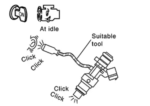
Without CONSULT-
Start the engine and let it idle.
-
Listen to each fuel injector operating sound.
Clicking sound should be heard.
Is the inspection result normal?
YES >>INSPECTION END
NO >>Perform trouble diagnosis for fuel injector and circuit, Refer to Diagnosis Procedure.
-
Other materials:
Heater and air conditioner (automatic)
AUTO (automatic) climate control button / temperature control dial (driver's
side)
Display screen
Heated seat switches (if so equipped)
SYNC button / temperature control dial (passenger's side)
A/C (air conditioner) button
Air recirculation button
A ...
B2f73-23 Clutch Switch
Dtc Description
DTC Description
DTC DETECTION LOGIC
DTC No.
CONSULT screen items
(Trouble diagnosis
content)
DTC detecting condition
...
Power Supply and Ground Circuit
A/c Auto Amp.
Diagnosis Procedure
Diagnosis Procedure
CHECK A/C AUTO AMP. GROUND CIRCUIT
FOR OPEN
Ignition switch OFF.
Disconnect A/C auto amp. connector.
...