Nissan Sentra B18 (2020-2025) Service Manual: Consult Checking System
Description
Description
Note:
This vehicle is diagnosed using the CONSULT-III plus.
-
When CONSULT is connected with a data link connector
 equipped on the
Nissan Sentra vehicle side, it will
communicate with the control unit equipped in the vehicle and then
enable various kinds of diagnostic tests.
equipped on the
Nissan Sentra vehicle side, it will
communicate with the control unit equipped in the vehicle and then
enable various kinds of diagnostic tests.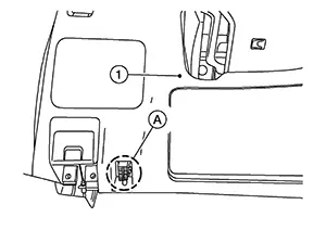

: Instrument lower panel LH
-
Refer to “CONSULT-III plus Operation Manual� for more information.
Function and System Application
Function and System Application
FUNCTION
|
Mode |
Function |
|---|---|
|
All DTC Reading |
Display all DTCs or diagnostic items that all ECUs are recording and judging. |
|
Work Support |
This mode enables a technician to adjust some devices faster and more accurately. |
|
Self Diagnostic Results |
Retrieve DTC from ECU and display diagnostic items. |
|
CGW Information |
Displays and sets the CGW status. Refer to CONSULT Function. |
|
Data Monitor |
Monitor the input/output signal of the control unit in real time. |
|
CAN Diagnosis |
This mode displays a network diagnosis result about CAN by diagram. |
|
CAN Diagnosis Support Monitor |
It monitors the status of CAN communication. |
|
Active Test |
Send the drive signal from CONSULT to the actuator. The operation check can be performed. |
|
ECU Identification |
Display the ECU identification number (part number etc.) of the selected system. |
|
Configuration |
Function to READ/WRITE Nissan Sentra vehicle configuration. |
|
SRT&P-DTC Confirmation |
The state of System Readiness Test (SRT) items, the presence or absence of permanent DTC*, and driving conditions can be checked. |
|
DTC work support |
DTC reproduction procedure can be performed speedily and precisely. |
|
Others |
Other results or histories, etc. that are recorded in ECU are displayed. |
*: Permanent DTC is not applied for regions where it is not mandated.
SYSTEM APPLICATION*1
|
System |
All DTC Reading |
Work Support |
Self Diagnostic Results |
CGW Information |
Data Monitor |
CAN Diagnosis |
CAN Diagnosis Support Monitor |
Active Test |
ECU Identification |
Configuration |
SRT&P-DTC Confirmation |
DTC work support |
Others |
|---|---|---|---|---|---|---|---|---|---|---|---|---|---|
|
ENGINE |
x |
x |
x |
x |
x |
x |
x |
x |
x |
- |
x |
x |
- |
|
TRANSMISSION |
x |
x |
x |
x |
x |
x |
x |
- |
x |
- |
x |
- |
|
|
AIR BAG |
x |
- |
x |
x |
x |
x |
- |
- |
x |
x |
- |
- |
|
|
METER / M&A |
x |
- |
x |
x |
x |
x |
- |
- |
x |
x |
- |
- |
|
|
AIR PRESSURE MONITOR1 |
x |
x |
x |
x |
x |
- |
- |
- |
x |
x |
- |
- |
- |
|
BCM |
x |
x |
x |
x |
x |
x |
x |
x |
x |
x |
- |
- |
- |
|
IPDM E/R |
x |
- |
x |
x |
x |
x |
- |
x |
x |
x |
- |
- |
- |
|
HVAC2 |
- |
x |
x |
x |
x |
x |
x |
x |
x |
- |
- |
- |
- |
|
HVAC3 |
- |
x |
x |
x |
x |
x |
x |
x |
x |
- |
- |
- |
- |
|
ABS |
x |
x |
x |
x |
x |
x |
- |
x |
x |
x |
- |
- |
- |
|
ICC / ADAS1 |
x |
x |
x |
x |
x |
x |
- |
x |
x |
x |
- |
- |
- |
|
LANE CAMERA |
x |
x |
x |
x |
x |
x |
- |
- |
x |
x |
- |
- |
- |
|
SIDE RADAR LEFT |
x |
- |
x |
x |
x |
x |
- |
x |
x |
x |
- |
- |
- |
|
SIDE RADAR RIGHT |
x |
- |
x |
x |
x |
x |
- |
x |
x |
x |
- |
- |
- |
|
TELEMATICS1 |
x |
- |
x |
x |
x |
x |
- |
- |
x |
- |
- |
- |
- |
|
HANDS FREE MODULE1 |
x |
x |
x |
x |
x |
x |
- |
- |
x |
x |
- |
- |
- |
|
SONAR1 |
x |
- |
x |
x |
x |
x |
- |
x |
x |
x |
- |
- |
- |
|
MULTI AV |
x |
- |
x |
x |
x |
x |
- |
- |
x |
x |
- |
- |
- |
|
EPS/DAST 3 |
x |
- |
x |
x |
x |
x |
- |
- |
x |
x |
- |
- |
- |
|
CHASSIS CONTROL |
x |
- |
x |
x |
x |
x |
- |
x |
x |
x |
- |
- |
- |
|
8CH CAN GATEWAY |
x |
- |
x |
x |
- |
x |
x |
- |
x |
- |
- |
- |
- |
x : Applicable
1: If so equipped
2: With auto A/C
3: With manual A/C
Consult Data Link Connector (dlc) Circuit
CONSULT Data Link Connector (DLC) Circuit
INSPECTION PROCEDURE
If the CONSULT cannot diagnose the system properly, check the following items.
|
Symptom |
Check item |
|---|---|
|
CONSULT cannot access any system. |
|
|
CONSULT cannot access individual system. (Other systems can be accessed.) |
|
The DDL2 circuits and CAN communication lines from DLC pins 6, 7 and 14 may be connected to more than one system. A short in a DDL circuit or CAN lines connected to a control unit in one system may affect CONSULT access to other systems.
For a complete DDL circuit layout, refer to:
-
Wiring Diagram
For a complete CAN line layout, refer to:
-
Wiring Diagram
Other materials:
C1f4f-82 Bcm Can Circuit 1
Dtc Description
DTC Description
DTC DETECTION LOGIC
DTC
CONSULT screen terms
(Trouble diagnosis
content)
DTC detection
conditi ...
Fuel Level Sensor Signal Circuit
Component Function Check
Component Function
Check
COMBINATION METER INPUT SIGNAL
CONSULT
Select “FUEL METER� in “Data Monitor� mode of “METER/M&A�.
Compare the ...
C1714-7b Low Tire Pressure Rr
Dtc Description
DTC Description
Note:
The Signal Tech II Tool [– (NI-50190)] can be used
to perform the following functions: Refer to the Signal Tech II User
Guide for additional information.
Activate and display TPMS sensor IDs
Display tire pressure rep ...