Nissan Sentra B18 (2020-2025) Service Manual: Harness Repair Procedure
Inspection
Inspection
Harness Repair Website and Resources
Wiring Harness and connector repair information including disassembly videos are located on the Harness Repair website. Links are found in ASIST and in the eWD. The website contains the following information:
-
Picture of connector with color, cavity quantity and connector family.
-
Part number of connector and part number of crimped terminal wire, if available.
-
Wire gauge and applicable solder sleeve.
-
Tool(s) required for procedure
-
Animation of removal procedure: Terminal locking tab location, removal of the retainer, and removal of the terminal

-
The crimped terminal wires, included in the kits, are the maximum gauge approved for use with the terminal. This wire may be larger than the existing wire in the Nissan Sentra vehicle.
-
The replacement connector body or wire color may differ from the original color.
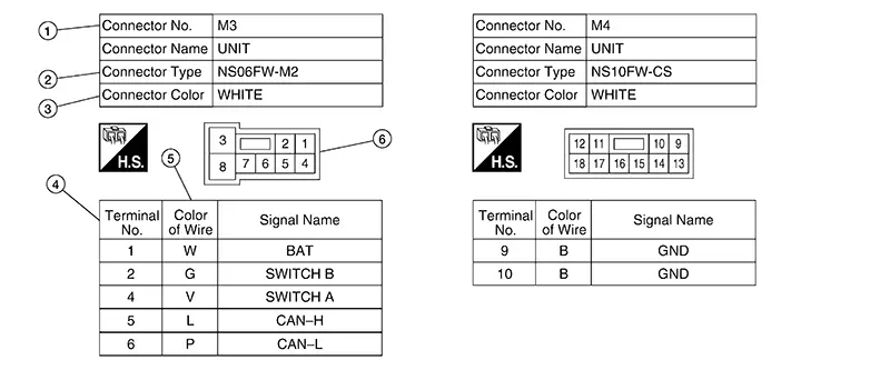
Connector Information
|
No. |
Item |
Description |
|
|---|---|---|---|
|
1 |
Connector number |
|
|
|
2 |
Connector type |
|
 |
|
3 |
Connector color |
|
|
|
4 |
Terminal number |
|
|
|
5 |
Wire color |
|
|
|
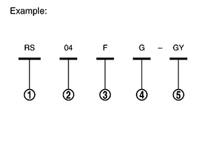
B = Black W = White R = Red G = Green L = Blue Y = Yellow LG = Light Green BG or BE = Beige BR = Brown |
LA = Lavender OR or O = Orange P = Pink PU or V (Violet) = Purple GY or GR = Gray SB = Sky Blue CH = Dark Brown DG = Dark Green |
||
|
|||
|
6 |
Connector |
|
|
 : Connector model
 : Cavity
 : Male (M) and female (F) terminals
 : Connector color
 : Special type
Using the Retainer/Terminal Removal Tool
Retainer/terminal removal tool use varies depending on which connector type is being serviced. Read all of the notes provided above prior to beginning a repair.
-
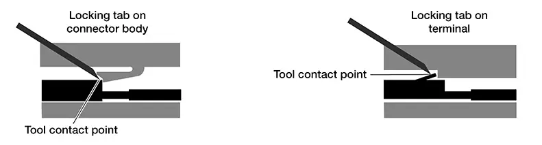
Performing terminal removal and installation should be easy. Watch the video and Read each step before beginning the procedure. Not reading each step may cause damage to connector retainer or locking tabs. Determine whether the terminal locking tab is integral into the connector or the terminal - this will affect the direction of the motion required to release the terminal.
-
Perform tool selection carefully – though a tool may appear to be the right shape, it may not be the correct tool for the connector.
-
Use of two blades (with spacer between them) will be required to release some terminals.
-
Unless otherwise directed, position the blade so the long side is against the connector.
-
In some cases, the wire must be pushed into the connector slightly to relieve pressure applied to the locking tab by the terminal. Not relieving this pressure may prevent the terminal from becoming unlocked.
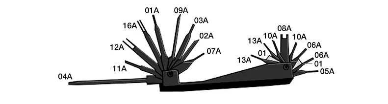
Retainer/Terminal Removal Tools
|
Retainer/Terminal Removal Tool |
|
|---|---|
|
NI-48817-1 Retainer/Terminal Removal Tool |
|
 |
|
|
NI-47003-11 Retainer Removal Tool |
|
 |
|
|
NI-47003-14 through NI-47003-35 Terminal Only Removal Tools (Use correct tool for the connector. Examples: NI-47003-14, NI-48817-25, NI-48817-29)) |
|
 |
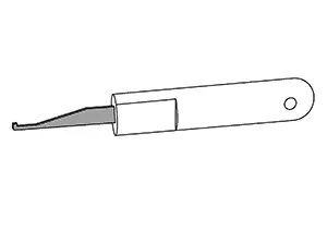
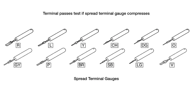
Using the Spread Terminal Gauge (STG)
-
Select the correct STG for the terminal to be tested.
-
Align the tip of the STG with the terminal.
-
While moving the connector slightly, gently apply pressure to the STG.
-
If the STG enters the terminal without compressing, replace the terminal.
-
If crimped terminal wire is not available, replace the connector assembly.
-
If neither part is available replace harness.
Do not attempt to modify/compress crimped terminal wire.
-
-
To view the video on a STG pass/fail test got to the harness repair website or follow the link in ASIST or in the eWD.
-
Use the Spread Terminal Gauge (STG) to inspect female terminals for loose fit.
-
Visually inspecting terminals is insufficient – using the STG test is the best method.
-
Use of the wrong STG may give inaccurate test results or cause damage to the terminal.
-
Refer to the Harness Repair Site to determine which STG should be used for each terminal.
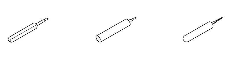
Spread Terminal Gauges (STG)
Bulk Wire
Bulk wire is available from Nissan in five sizes to make a correct repair. If the exact size is not available, go up one wire size. Nissan bulk wire is Hi-Temp and can be used in exterior or interior applications.
Note:
Using Nissan wire is required for warranty repairs.
Use solder sleeve chart, as reference for proper wire/solder sleeve application.
-
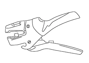
Automatic Wire Stripper
CAUTION:
To avoid the risk of minor personal injury:
-
Always wear approved eye protection to prevent eye injury.
-
Do not use non-insulated, plastic-dipped or slip-on plastic handles that are NOT intended for protection against electrical shock without the proper PPE, to prevent electrocution.
-
Never repair live electrical circuits, to prevent electrocution.
Automatic Wire Stripper
Part # NI-35615
-
-
Wire Stripper Repair Procedures
Note:
To avoid damaging the wiring harness, be careful not to cut the wires when using automatic wire strippers. On small gauge wire (gauge 26-30) manual wire strippers are recommended.
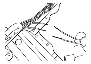
The following procedure describes how to use the automatic wire stripper, to remove insulation from the wire without nicking or fraying.
-
Choose and install the correct stripper die for the wire gauge you are repairing.
-
Adjust the wire stop to the desired stripping length. The recommended length for Blue Solder Sleeves (12-16 AWG) is approximately 10 mm (0.4 in.).
-
With the open side of the jaws toward you (wire stop to the right), place the wire in the appropriate size stripping hole with the end touching the wire stop. Refer to the blade for AWG and mm size markings.
-
Squeeze the handles together to strip the wire. Release pressure from the handles and remove the wire.
-
Solder Sleeves
|
CABLE SIZE (GAUGE AWG) |
SOLDER SLEEVE COLOR |
SOLDER SLEEVE IMAGE |
|---|---|---|
|
26-30 |
White |
 |
|
18-24 |
Red |
 |
|
16-12 |
Blue |
 |
Solder Sleeve Installation Steps
IMPORTANT: Jacketed and/or shielded wires cannot be repaired.
-
Check the gauge of the wire that is to be spliced, to determine correct solder sleeve size.
-
Strip approximately 10 mm (about 3/8 inch) of insulation from the wires that will be attached.
-
Slide the Solder Sleeve over one of the wires that will be connected.
-
Twist the two wires together
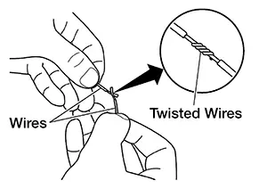
-
Position the solder ring in relation to the twisted wires.
 Note:
Note:
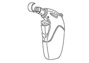
For the next step, do not use an electric type soldering tool. An electric type soldering tool may generate a current that can damage a control unit that might be connected to the circuit.
-
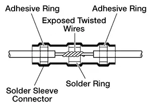
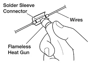
"Install" the solder sleeve connector by shrinking it to the wire with essential tool Flameless Heat Gun NI-46538 or similar flameless heating tool.
"Installing" the solder sleeve connector will:
-
Melt the solder (silver ring inside the solder sleeve connector) into the exposed twisted wire area.
-
Melt the sealant (white, red or blue rings inside the solder sleeve connector) onto the wires.
-
Shrink the remainder of the solder sleeve connector to the wire.
-
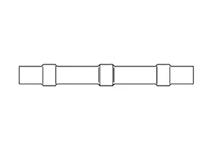
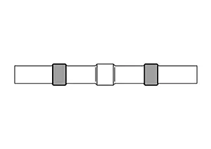
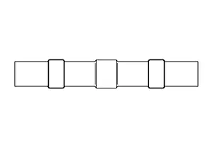
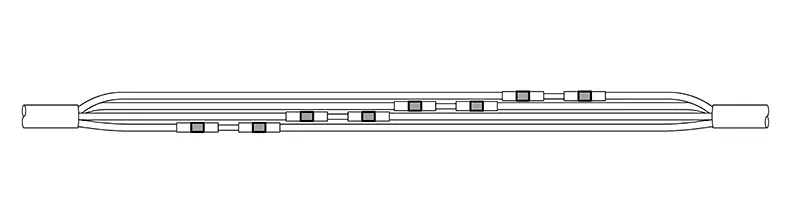
When repairing a wire bundle that has been damaged it works best to stagger the solder sleeves:
Miscellaneous Supplemental Service Parts
OE replacement parts available: body clips, felt tape & corrugared tubing/loom.
|
Part |
Application |
Nissan Parts Available |
Picture |
|---|---|---|---|
|
Electrical Tape |
Cover solder repairs, secure wire loom |
No |
– |
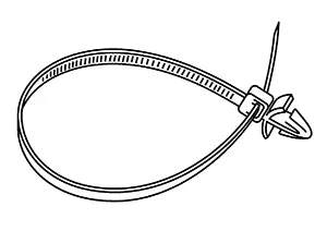
|
Body Clips |
Interior use to prevent squeaks, rattles, chafing Several Size Available |
Yes |
 |
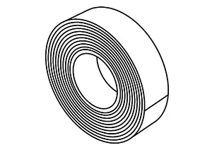
|
Felt Tape |
Interior use to prevent squeaks, rattles, chafing |
Yes |
 |
|
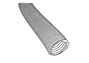
Wire Loom |
Protect exterior wires, available in 2 sizes: 3/8" and 5/8" |
Yes |
 |
There are 2 corrugated tubing tools that are used to aid in the installation of corrugated tubing:
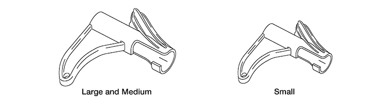
Tools are available through Nissan Tool & Equipment Website.
Harness Replacement Guidelines
IMPORTANT: Observe all applicable safety precautions described in the service manual for the electrical systems that are being repaired.
Replace the wiring harness ONLY when the Nissan Sentra vehicle concern involves any one of the following conditions:
-
The wiring harness circuits are related to HEV / EV High Voltage.
-
The estimated cost of the repair exceeds the cost of replacing the entire wiring harness.
-
The Nissan Sentra vehicle is damaged by flood or thermal incident.
-
The wiring harness was severely damaged due to a car accident.
-
The appropriate components are not available to order.
-
The wiring harness replacement is required from another TSB.
-
The wiring harness repair is in the shielded area of a circuit.
-
The wiring harness needing repair is USB, Coaxial, or Antenna Feeder wiring.
Connector Body Replacement
Connector Body Replacement
All Connector Body Replacement Except SRS
Replacement/Supplemental Repair
This type of repair is necessary when a connector body or locking lever is damaged causing it to not lock securely, hold terminals or pins in place, or is deformed allowing foreign material intrusion (example: water and/or corrosion).
-
Damaged Lever: Some larger connectors have a locking lever that secures them to the mating connector; ECM, TCM, SMJ (Super Multiple Junction), ABS etc. If you inspect these types of connectors and find that the issue is related to the locking lever, the lever may be replaced (if available).
-
Identify the connector type, in the Harness Repair Web Page, and obtain the correct connector body and crimpled terminal/pin ends.
-
Use the disassembly instructions/animation to remove and replace the locking lever.
-
-
Damaged Connector Body
-
Identify the connector type, in the Harness Repair Web Page, and obtain the correct connector body and crimpled terminal/pin ends.
Note:
If the connector body is unavailable, send feedback using the link on the Harness Repair Web Page, submit claim in Salesforce, and wait for next steps.
-
Take the acquired connector body and plug it into the corresponding connection, to ensure you have the correct connector body.
-
Remove any tape from around the wire and corrugated tubing, to allow for ample working space.
-
De-pin the terminals from damaged connector body, using the steps provided in the terminal/pin repair section.
Note:
Pins on multiple pin connectors should be transferred from the old to the new connector one at a time.
-
Install the newly assembled connector body harness into the corrugated tubing. Use tape to secure the wires inside the tubing.
-
Plug in the connector and confirm that it firmly locks into place by lightly pulling on the connector body.
-
-
Terminal/Pin Replacement:
IMPORTANT: Jacketed and/or shielded wires cannot be repaired. This type of repair is necessary when you find either a pin (male) is bent, broken, corroded, etc., or a terminal (female) has damage, is spread, corroded, etc.
Note:
Terminal repair is not available for SRS.
-
Using the eWD find the connector type and then use that information to acquire the correct terminal/pin part number and terminal/pin removal tool information.
-
Following instructions in harness guide on how to properly remove a Terminal/Pin from connector body making sure to not damage connector body or Terminal/Pin locking tab.
-
Once Terminal/Pin is removed match up replacement Terminal/Pin to properly cut length not allowing excess wire.
-
Strip one end of new crimped Terminal/Pin wire and of harness circuit.
-
Follow Solder Sleeve Installation Steps to install solder sleeves.
-
Install new crimped Terminal/Pin into Connector Body making sure to place in correct cavity.
-
SRS Related Connectors Pigtail Replacement
IMPORTANT: Jacketed and/or shielded wires cannot be repaired.
SRS Connector Body: This repair is used when the root cause is related to an SRS connector body or terminal issue. SRS connectors can only be repaired by replacing the connector body pigtail assembly. Terminal repair is not available for SRS. Do not attempt to dissemble SRS connectors and is not an approved repair method.
-
Identify the connector body type in the Harness Repair Web Page and then obtain the appropriate part.
Note:
If the connector body pigtail is unavailable, send feedback using the link on the Harness Repair Web Page, submit claim in Salesforce, and wait for next steps.
-
Take the acquired connector body pigtail and plug it into the corresponding connection, to ensure you have the correct connector.
-
Remove any tape from around the wire and corrugated tubing, to allow for ample working space.
-
Cut the wire to allow enough room to stagger the solder sleeves, and to position the new connector to approximately the original location.
-
Strip the wire accordingly, and follow the Solder Sleeve Installation Steps to install solder sleeves correctly.
-
Install the new connector body pigtail into the corrugated tubing of the harness, and then tape it to securely hold the corrugated tubing around the wires.
-
Plug in the new connector body pigtail and confirm that it firmly locks into place by lightly pulling on the connector body.
Wire Overlay - All Systems including SRS
IMPORTANT: Jacketed and/or shielded wires cannot be repaired.
-
Wire Overlay Guidelines:
Note:
Nissan bulk wire is Hi-temp and can be used in the exterior or interior of the Nissan Sentra vehicle. Using Nissan wire is required for warranty repairs.
This type of repair is necessary when it has been confirmed that a certain circuit in the harness is faulty.
-
Open the harness on both ends, of where you plan to make the repair, allowing sufficient room to work.
-
Cut the ends of the incident wire to isolate the circuit.
-
Cut piece of the same gauge wire to length, from Nissan provided wire spools. If the exact gauge wire is not available, go up one size.
-
Strip one end of the new wire, and of harness circuit, and then follow the Solder Sleeve Installation Steps to install solder sleeves.
-
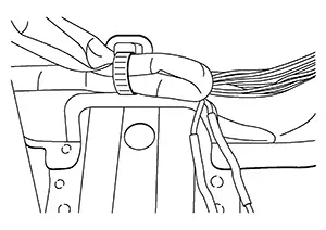
Next lay the wire on the outside of the harness, making sure to cover the exposed wire in the corrugated tubing along the whole length.
-
Secure the corrugated tubing with tape to the harness to ensure the wire follows the harness path.
-
Strip the end of the wire and of other end of the harness circuit and then follow the Solder Sleeve Installation Steps to install solder sleeves correctly.
-
-
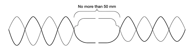
Twisted Pair Circuits
Harness specification for a twisted wire circuits defines a twist pitch, or twists-per-length requirement, which is to improve signal quality & noise rejection of the circuit.
When repairing a twisted pair circuit, do not un-twist the damaged circuit pair more than needed to repair the circuit, and never more than 50 mm.
Other materials:
Diagnosis System (bcm)
Common Item
Consult Function (bcm - Common Item)
CONSULT Function (BCM - COMMON ITEM)
BCM
Refer to CONSULT Function (BCM - COMMON ITEM).
Int Lamp
Consult Function (bcm - Int Lamp)
CON ...
Operation
Switch Name and Function
Switch Name and Function
STEERING SWITCH
The steering switch is located on the steering
wheel.
Transmits the steering switch signal to the
combination meter.
...
A/c Switch Assembly Signal Circuit
Diagnosis Procedure
Diagnosis Procedure
CHECK WITH SELF DIAGNOSTIC RESULT FUNCTION
CONSULT
Select “Self Diagnostic Result” mode of “HVAC”.
Check DTC.
...