Nissan Sentra Service Manual: M&A branch line circuit
Diagnosis procedure
1.Check connector
- Turn the ignition switch off.
- Disconnect the battery cable from the negative terminal.
- Check the terminals and connectors of the combination meter for damage, bend and loose connection (unit side and connector side).
Is the inspection result normal? Yes >> go to 2.
No >> repair the terminal and connector.
2.Check harness for open circuit
- Disconnect the connector of combination meter.
- Check the resistance between the combination meter harness connector terminals.
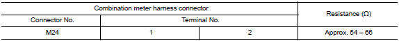
Is the measurement value within the specification? Yes >> go to 3.
No >> repair the combination meter branch line.
3.Check power supply and ground circuit
Check the power supply and the ground circuit of the combination meter. Refer to MWI-52, "COMBINATION METER : Diagnosis Procedure".
Is the inspection result normal? YES (Present error)>>Replace the combination meter. Refer to MWI-77, "Removal and Installation".
YES (Past error)>>Error was detected in the combination meter branch line.
NO >> Repair the power supply and the ground circuit.
 Eps branch line circuit
Diagnosis Procedure
1.Check connector
Turn the ignition switch off.
Disconnect the battery cable from the negative terminal.
Check the terminals and connectors of the eps control unit for dam ...
 Strg branch line circuit
Diagnosis procedure
1.Check connector
Turn the ignition switch off
Disconnect the battery cable from the negative terminal.
Check the terminals and connectors of the steering angle sensor for ...
Other materials:
Unit disassembly and assembly
TORQUE CONVERTER AND CONVERTER HOUSING OIL SEAL
Exploded View
Transaxle assembly
Torque converter
Converter housing oil seal
: Apply CVT Fluid
Disassembly
Remove transaxle assembly.
Remove torque converter.
CAUTION:
Do not damage the bushing on the inside of torque con ...
Regulatory Information
FCC Regulatory information
CAUTION: To maintain compliance with
FCC’s RF exposure guidelines, use only the
supplied antenna. Unauthorized antenna,
modification, or attachments could damage
the transmitter and may violate FCC regulations.
Operation is subject to the following two cond ...
Component parts
STARTING SYSTEM (WITH INTELLIGENT KEY)
Component Parts Location
Starter motor
Transmission range switch (CVT Models)
IPDM E/R (view with air inlet duct
removed)
Clutch interlock switch (M/T Models)
ECM
BCM (view under instrument panel,
left side of vehicle)
Component Descri ...
