Nissan Sentra Service Manual: Front door glass
Removal and Installation
REMOVAL
WARNING:
- Before servicing, turn ignition switch OFF, disconnect both battery terminals and wait at least three minutes.
- Do not use air tools or electric tools for servicing.
NOTE:
LH front door panel shown; RH side similar
- Disconnect the battery positive and negative terminal. Refer to PG-50, "Removal and Installation (Battery)".
- Remove the front door finisher. Refer to INT-15, "Removal and Installation".
- Remove the vapor barrier.
CAUTION:
Use care to not damage or tear vapor barrier during removal.
- Temporarily reconnect both battery terminals and the main power window and door lock/unlock switch (LH door) or power window and door lock/unlock switch (RH door) to raise/lower the door glass until the door glass bolts can be seen through the access holes.
- Remove the front door regulator to glass bolts (A).
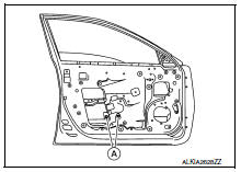
- While holding the front door glass, raise it at the rear end to pull the front door glass out of the sash toward the outside of the door.
INSTALLATION
Installation is in the reverse order of removal.
FRONT DOOR GLASS INSPECTION AFTER INSTALLATION
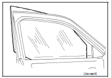
- Check that the door glass is securely set into the glass run groove.
- Lower the door glass slightly [approximately 10 to 20 mm (0.4 to 0.8 in)] and check that the clearance to the sash is parallel. If the clearance between the door glass and sash is not parallel, loosen the regulator bolts, guide rail bolts, and door glass and guide rail bolts to correct the glass position.
Inspection and Adjustment
SYSTEM INITIALIZATION (IF NECESSARY)
- If any of the following occur, system initialization must be performed.
- Electric power supply to power window switch or motor is interrupted by blown fuse or disconnecting battery cable, etc.
- Removal and installation of the regulator assembly.
- Removal and installation of the motor from the regulator assembly.
- Removal and installation of the harness connector of the power window switch.
- Operation of the regulator assembly as a unit.
- Removal and installation of the door glass.
- Removal and installation of the door glass run.
- Window is partly opened and or closed multiple times with out being fully closed.
- To perform system initialization, refer to PWC-29, "Work Procedure".
INSPECT THE FUNCTION OF THE ANTI-PINCH SYSTEM.
To inspect the anti-pinch system, refer to PWC-29, "Work Procedure".
 Windshield glass
Exploded View
Windshield glass molding
Spacer
Rubber dam
Windshield glass
Windshield insulator
Front pillar finisher
Instrument panel
Cowl top cover
Roof panel
Cowl top
Bo ...
 Front regulator
Exploded View
Front door panel
Front door glass channel front
Front door glass regulator
Front door glass regulator motor
Front door glass channel rear
Front door glass
Front door ...
Other materials:
Basic inspection
Diagnosis and repair workflow
Trouble diagnosis flow chart
Trouble diagnosis procedure
Interview with customer
Interview with the customer is important to detect the root cause of can
communication system errors and to
understand vehicle condition and symptoms for proper trouble diagnosi ...
Normal operating condition
Compass
Compass : description
Compass
The electronic compass is highly protected from changes in most magnetic
fields. However, some large
changes in magnetic fields can affect it. Some examples are (but not limited
to): high tension power lines,
large steel buildings, subways, steel ...
The steering switch (meter control switch) is inoperative
Description
If any of the following malfunctions is found for the steering switch (meter
control switch) operation.
All switches are inoperative
The specified switch cannot be operated
Diagnosis procedure
1.Check steering switch signal circuit
Check the steering switch signal circuit. ...
