Nissan Sentra Service Manual: Windshield glass
Exploded View
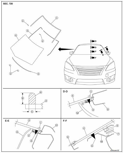
- Windshield glass molding
- Spacer
- Rubber dam
- Windshield glass
- Windshield insulator
- Front pillar finisher
- Instrument panel
- Cowl top cover
- Roof panel
- Cowl top
- Body side outer
- Headlining
- Adhesive
- 12 +2.0 mm (0.5 +0.08 in)
- 7 +2.0 mm (0.3 +0.08 in)
Removal and Installation
REMOVAL
- Partially remove the headlining (front edge). Refer to INT-40, "Removal and Installation".
- Remove inside mirror. Refer to MIR-16, "Removal and Installation".
- Remove the cowl top cover. Refer to EXT-26, "Removal and Installation".
- Remove windshield glass using piano wire or power cutting tool (A) and an inflatable pump bag (B).
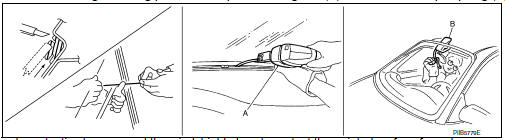
- Apply protective tape around the windshield glass to protect the painted surface from damage.
- If the windshield glass is to be reused, mark the body and the glass with matching marks.
- Minimum adhesive coating amount 8 +3,-0 g/100 mm (0.28 +0.11,-0 oz/3.9 in) all around.
WARNING:
When cutting the glass from the vehicle, always wear safety glasses and heavy gloves to help prevent glass splinters from entering your eyes or cutting your hands.
CAUTION:
- Be careful not to scratch the glass when removing.
- Do not set or stand the glass on its edge. Small chips may develop into cracks.
- Apply protective tape around the windshield glass to protect the painted surface from damage.
INSTALLATION
Installation is in the reverse order of removal.
- If repainting near the windshield flange area, protect the flange adhesion area by masking the flange.
- Use a genuine NISSAN Urethane Adhesive Kit (if available) or equivalent and follow the instructions furnished with it.
- Adhesive shall be continuously applied to assure watertightness. Glass installation shall be finished within five minutes after applying the adhesive.
- The start and finish of the urethane adhesive application should be located at the bottom to assure watertightness.
- While the urethane adhesive is curing, open a door window. This will prevent the glass from being forced out by passenger compartment air pressure when a door is closed.
- The molding must be installed securely to the windshield glass to avoid looseness and will leave no gap.
- Inform the customer that the vehicle should remain stationary until the urethane adhesive has completely cured (preferably 24 hours). Curing time varies with temperature and humidity.
WARNING:
- Keep heat and open flames away as primers and adhesive are flammable.
- The materials contained in the kit are harmful if swallowed, and may irritate skin and eyes. Avoid contact with the skin and eyes.
- Use in an open, well ventilated location. Avoid breathing the
vapors. They can be harmful if inhaled.
If affected by vapor inhalation, immediately move to an area with fresh air.
- Driving the vehicle before the urethane adhesive has completely cured may affect the performance of the windshield in case of an accident.
CAUTION:
- Do not use an adhesive which is past its usable term. Shelf life of this product is limited to six months after the date of manufacture. Carefully adhere to the expiration or manufacture date printed on the box or product.
- Keep primers and adhesive in a cool, dry place. Ideally, they should be stored in a refrigerator.
- Do not leave primers or adhesive cartridge unattended with their caps open or off.
- The vehicle should not be driven for at least 24 hours or until the urethane adhesive has completely cured. Curing time varies depending on temperature and humidity. The curing time will increase under lower temperature and lower humidity.
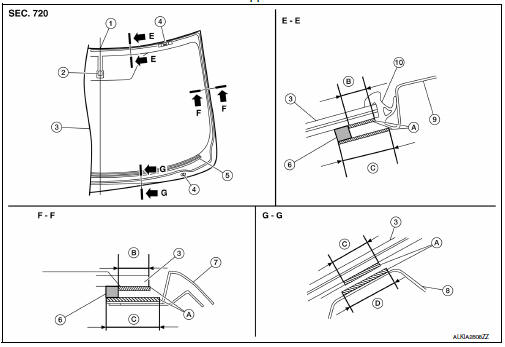
Primer Application
- Vehicle center
- Inside mirror base
- Windshield glass
- Spacer
- Windshield insulator
- Rubber dam
- Front pillar outer panel
- Cowl top
- Roof panel
- Windshield glass upper molding
- Primer portion
- 8.0 mm (0.31 in)
- 20 mm (0.8 in)
- 30 mm (1.2 in)
REPAIRING WATER LEAKS FOR WINDSHIELD
- Leaks can be repaired without removing and reinstalling glass.
- If water is leaking between the urethane adhesive material and body or glass, determine the extent of leakage.
- This can be done by applying water to the windshield area while pushing glass outward.
- To stop the leak, apply primer (if necessary) and then urethane adhesive to the leak point.

 Front door glass
Removal and Installation
REMOVAL
WARNING:
Before servicing, turn ignition switch OFF, disconnect both
battery terminals and wait at least three
minutes.
Do not use air tools or electric ...
Other materials:
A-bag branch line circuit
Diagnosis procedure
Warning:
Always observe the following items for preventing accidental
activation.
Before servicing, turn ignition switch off, disconnect battery
negative terminal, and wait 3 minutes
or more. (To discharge backup capacitor.)
Never use unspecified tester or other me ...
U1000 Can comm circuit
Description
CAN (Controller Area Network) is a serial communication line for real-time
application. It is an on-vehicle multiplex
communication line with high data communication speed and excellent malfunction
detection ability.
Many electronic control units are equipped onto a vehicle, an ...
Service Notice or Precautions for Steering System
In case of removing steering gear assembly, make the final
tightening with grounded and unloaded vehicle
condition, and then check wheel alignment.
Observe the following precautions when disassembling.
Before disassembly, thoroughly clean the outside of the
unit.
...
