Nissan Sentra Service Manual: Eps branch line circuit
Diagnosis Procedure
1.Check connector
- Turn the ignition switch off.
- Disconnect the battery cable from the negative terminal.
- Check the terminals and connectors of the eps control unit for damage, bend and loose connection (unit side and connector side).
Is the inspection result normal? Yes >> go to 2.
No >> repair the terminal and connector.
2.Check harness for open circuit
- Disconnect the connector of EPS control unit.
- Check the resistance between the eps control unit harness connector terminals.
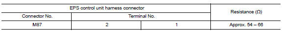
Is the measurement value within the specification? Yes >> go to 3.
No >> repair the eps control unit branch line.
3.Check power supply and ground circuit
Check the power supply and the ground circuit of the EPS control unit. Refer to STC-22, "Diagnosis Procedure".
Is the inspection result normal? YES (Present error)>>Replace the EPS control unit. Refer to STC-39, "Removal and Installation".
YES (Past error)>>Error was detected in the EPS control unit branch line.
NO >> Repair the power supply and the ground circuit.
 Dlc branch line circuit
Diagnosis Procedure
1.Check connector
Turn the ignition switch off.
Disconnect the battery cable from the negative terminal
Check the terminals and connectors of the data link connector for
...
 M&A branch line circuit
Diagnosis procedure
1.Check connector
Turn the ignition switch off.
Disconnect the battery cable from the negative terminal.
Check the terminals and connectors of the combination meter for da ...
Other materials:
P1588 G Sensor
DTC Logic
DTC DETECTION LOGIC
DTC
CONSULT screen terms
(Trouble diagnosis content)
DTC detection condition
Possible causes
P1588
G Sensor
(Gravity Sensor Circuit)
When the following diagnosis conditions are
satisfied and the detection conditi ...
Vehicle Recovery (Freeing a Stuck Vehicle)
Front
Remove the hook cover from the bumper using a remover tool.
Securely install the vehicle recovery hook stored with jacking
tools.
Check that the hook is properly secured in the stored place after use.
WARNING:
Stand clear of a stuck vehicle.
Do not spin your tires at high s ...
The fuel gauge indicator does not operate
Description
Fuel gauge will not indicate from a certain position.
Diagnosis procedure
1.CHECK FUEL LEVEL SENSOR SIGNAL CIRCUIT
Check the fuel level sensor signal circuit. Refer to MWI-58, "Diagnosis
Procedure".
Is the inspection result normal?
YES >> GO TO 2.
NO >> ...
