Nissan Sentra Service Manual: Dlc branch line circuit
Diagnosis Procedure
1.Check connector
- Turn the ignition switch off.
- Disconnect the battery cable from the negative terminal
- Check the terminals and connectors of the data link connector for damage, bend and loose connection (connector side and harness side).
Is the inspection result normal? Yes >> go to 2.
No >> repair the terminal and connector.
2.Check harness for open circuit
Check the resistance between the data link connector terminals.
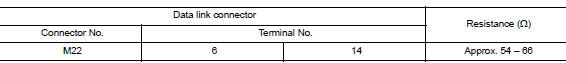
Is the measurement value within the specification? YES (Present error)>>Check CAN system type decision again.
YES (Past error)>>Error was detected in the data link connector branch line circuit.
NO >> Repair the data link connector branch line.
 A-bag branch line circuit
Diagnosis procedure
Warning:
Always observe the following items for preventing accidental
activation.
Before servicing, turn ignition switch off, disconnect battery
negative terminal, and w ...
 Eps branch line circuit
Diagnosis Procedure
1.Check connector
Turn the ignition switch off.
Disconnect the battery cable from the negative terminal.
Check the terminals and connectors of the eps control unit for dam ...
Other materials:
CVT Fluid filter
Exploded View
Transaxle assembly
CVT fluid filter
Fluid filter cover
CVT fluid
Removal and Installation
REMOVAL
Remove neighboring parts of CVT fluid filter.
Remove fluid filter cover mounting bolt (A).
Remove fluid filter cover (1) from transaxle by rotating leftw ...
Body side trim
Exploded View
Rear body side welt
Front body side welt
Tether clip
Front pillar finisher
Metal clip
Dash clip
Dash side finisher
Harness protector
Front kicking plate inner
Center pillar lower finisher
Rear kicking plate inner
Cap
Center pillar upper finisher
Rear p ...
Brake fluid
Drain and Refill
CAUTION:
Do not spill or splash brake fluid on painted surfaces. Brake
fluid may damage paint. If brake fluid is
splashed on painted areas, wash it away with water immediately.
Prior to repair, turn the ignition switch OFF, disconnect the ABS
actuator and electric uni ...
