Nissan Sentra Service Manual: C1164, C1165, C1166, C1167 CV/SV System
DTC Logic
Dtc detection logic
| DTC | Display Item | Malfunction detected condition | Possible causes |
| C1164 | CV 1 | When a malfunction is detected in cut valve 1. |
|
| C1165 | CV 2 | When a malfunction is detected in cut valve 2. | |
| C1166 | SV 1 | When a malfunction is detected in suction valve 1. | |
| C1167 | SV 2 | When a malfunction is detected in suction valve 2. |
DTC CONFIRMATION PROCEDURE
1.CHECK SELF DIAGNOSTIC RESULT
 With CONSULT.
-
Turn ignition switch OFF to ON.
-
Perform self diagnostic result.
Is DTC C1164, C1165, C1166 or C1167 detected? YES >> Proceed to diagnosis procedure. Refer to BRC-85, "Diagnosis Procedure".
NO >> Inspection End.
Diagnosis Procedure
Regarding Wiring Diagram information, refer to BRC-44, "Wiring Diagram".
1.CONNECTOR INSPECTION
-
Turn ignition switch OFF.
-
Disconnect ABS actuator and electric unit (control unit) connector.
-
Check connector and terminals for deformation, disconnection, looseness or damage.
Is the inspection result normal? YES >> GO TO 2.
NO >> Repair or replace as necessary.
2.Check abs actuator and electric unit (control unit) battery power supply
Check voltage between ABS actuator and electric unit (control unit) connector E33 terminal 25 and ground.
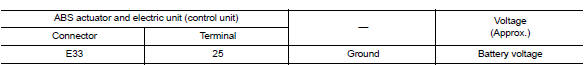
Is the inspection result normal? Yes >> go to 3.
No >> repair or replace malfunctioning components.
3.Check abs actuator and electric unit (control unit) ground circuit
Check continuity between abs actuator and electric unit (control unit) connector e33 terminals 13, 38 and ground.
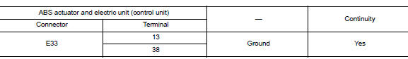
Is the inspection result normal? Yes >> replace abs actuator and electric unit (control unit). Refer to brc-110, "removal and installation".
No >> repair or replace malfunctioning components.
 C1155 BR Fluid level low
DTC Logic
Dtc detection logic
Dtc
Display item
Malfunction detected condition
Possible cause
C1155
C1155 br fluid level low
Brake fluid level is low or communication l ...
 U1000 CAN Comm circuit
DTC Logic
DTC DETECTION LOGIC
DTC
Display Item
Malfunction detected condition
Possible causes
U1000
CAN COMM CIRCUIT
When CAN communication signal is not continuously
...
Other materials:
Rear window glass
Exploded View
Rear window glass
Spacer
Rubber dam
Body side outer
Headlining
Roof panel
Trunk lid
Adhesive
12 mm (0.5 in)
7 mm (0.3 in)
2.0 mm (0.08 in)
3 mm (0.1 in)
Removal and Installation
REMOVAL
Partially remove the rear of the headlining (rear edge). R ...
Fuel level sensor signal circuit
Description
The fuel level sensor unit and fuel pump detects the approximate fuel level
in the fuel tank and transmits the
fuel level signal to the combination meter.
Component function check
1.Combination meter input signal
Select meter/m&a on consult.
Using FUEL METER of DATA MONI ...
Removal and installation
Hood
Hood assembly
Hood assembly : exploded view
Hood hinge (LH/RH)
Hood assembly
Hood bumper rubber
Hood seal
Hood insulator
Hood support rod
Hood support rod clamp
Clip
Hood assembly : removal and installation
CAUTION:
Use two people when removing or installing h ...
