Nissan Sentra B18 (2020-2025) Service Manual: Combination Switch
Exploded View
|
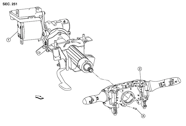
1. |
Steering column assembly |
2. |
Combination switch |
A. |
Screw |
|
|
Front |

Shown with the steering wheel removed for clarity only.
Removal and Installation
REMOVAL
CAUTION:
Do not use air or electric tools when removing or installing the combination switch.
Remove the spiral cable. Refer to Removal and Installation.
Disconnect the harness connector from the combination switch.
Remove the screw from the combination switch and remove the combination switch.
INSTALLATION
Installation is in the reverse order of removal.
CAUTION:
-
After the work is completed, make sure no system malfunction is detected by air bag warning lamp.
-
In case a malfunction is detected by the air bag warning lamp, reset with the self-diagnosis function and delete the memory with CONSULT.
-
If a malfunction is still detected after the above operation, perform self-diagnosis to repair malfunctions. Refer to Description.
 Rear Combination Lamp (trunk Lid Side)
Exploded View
Exploded View
1.
Trunk lid
2.
...
 Hazard Switch
Exploded View
Exploded View
1.
Center ventilator
grille
...
Other materials:
C1f00-49 Control Unit
Dtc Description
DTC Description
DTC DETECTION LOGIC
DTC
CONSULT screen terms
(Trouble diagnosis
content)
DTC detection
...
Service Data and Specifications (sds)
Idle Speed : Service Data
IDLE SPEED : Service Data
Transmission
Condition
Specification
(Approx.)
CVT
...
Precautions for Suspension
Precautions for Suspension
When installing rubber bushings, the final
tightening must be carried out under unladen conditions with tires
on ground. Spilled oil might shorten the life of rubber bushings.
Be sure to wipe off any spilled oil.
...
