Nissan Sentra Service Manual: Brake pedal
Exploded View
WITHOUT BRAKE PEDAL POSITION SWITCH
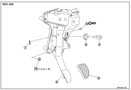
- Snap pin
- Brake pedal assembly
- Brake pedal pad
- Stop lamp switch
- Clip
- Clevis pin
 Apply multi-purpose grease.
WITH BRAKE PEDAL POSITION SWITCH
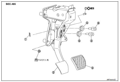
- Snap pin
- Brake pedal assembly
- Brake pedal pad
- Brake pedal position switch
- Clip
- Stop lamp switch
 Apply multi-purpose grease.
Removal and Installation
REMOVAL
- Remove instrument lower panel LH. Refer to IP-21, "Removal and Installation".
- Remove steering column lower cover. Refer to IP-16, "Removal and Installation".
- Disconnect the harness connectors from the brake pedal position switch (if equipped) and the stop lamp switch.
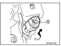
- Rotate the stop lamp switch and the brake pedal position switch (if equipped) (1) counter clockwise to remove.
- Disconnect the accelerator pedal harness connector and harness clip.
- Remove snap pin and clevis pin from clevis on brake booster.
- Remove the brake pedal assembly.
CAUTION:
Secure the brake booster and brake master cylinder to avoid damage to components.
- Remove accelerator pedal from brake pedal assembly. Refer to ACC-3, "Removal and Installation".
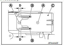
INSPECTION AFTER REMOVAL
Check for the following items and replace the brake pedal assembly, if necessary.
- Check the brake pedal upper rivet (A) for damage or wear.
- Check the brake pedal for bend, damage, and cracks on the welded parts.
- Check the lapping length (D) of sub-bracket (B) and slide plate (C).
Lapping length (D) : 6.5 mm (0.256 in) or more
INSTALLATION
Installation is in the reverse order of removal.
CAUTION:
- Do not reuse the clevis pin.
- Install the clevis pin in the proper direction. Refer to BR-22, "Exploded View".
- Apply multi-purpose grease to the clevis pin and the mating faces, if necessary.
ADJUSTMENT AFTER INSTALLATION
- Adjust each item of brake pedal after installing the brake pedal assembly to the vehicle. Refer to BR-15, "Adjustment".
- Perform the release position learning of the accelerator pedal. Refer to EC-138, "Work Procedure".

 Brake piping
FRONT
FRONT : Exploded View
Brake tube
ABS actuator and electric unit (control
unit)
Connector
Connector bracket
Master cylinder assembly
Brake booster
Lock plate
Brake hose
...
Other materials:
Hazard warning flasher switch
Push the switch on to warn other drivers when
you must stop or park under emergency conditions.
All turn signal lights flash.
WARNING
If stopping for an emergency, be sure to
move the vehicle well off the road.
Do not use the hazard warning flashers
while moving on th ...
DTC/circuit diagnosis
U1000 CAN COMM CIRCUIT
Description
Refer to lan-7, "can communication system : system description".
Dtc logic
Dtc detection logic
Note:
U1000 can be set if a module harness was disconnected and reconnected,
perhaps during a repair. Confirm
that there are actual CAN diagnostic symp ...
Front fog lamp circuit
Description
The ipdm e/r (intelligent power distribution module engine room) controls the
front fog lamp relay based on
inputs from the bcm over the can communication lines. When the front fog lamp
relay is energized, power
flows from the front fog lamp relay in the ipdm e/r to the front fog ...
