Nissan Sentra Service Manual: Brake piping
FRONT
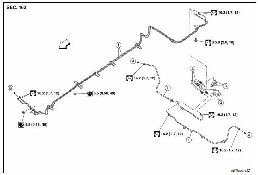
FRONT : Exploded View
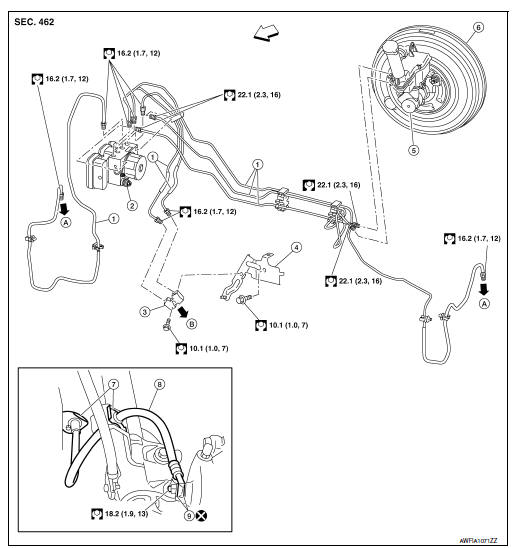
- Brake tube
- ABS actuator and electric unit (control unit)
- Connector
- Connector bracket
- Master cylinder assembly
- Brake booster
- Lock plate
- Brake hose
- Copper sealing washer
- To front brake hose
- To rear brake pipe
 Front
Front
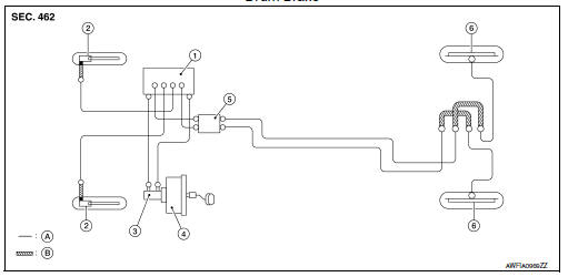
FRONT : Hydraulic Piping
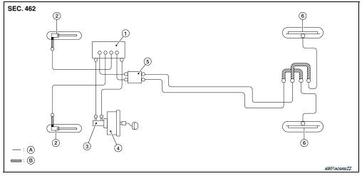
Drum Brake
- ABS actuator and electric unit (control unit)
- Front disc brake
- Master cylinder assembly
- Brake booster
- Connector
- Rear drum brake
- Brake tube
- Brake hose
 Flare nut
 Union bolt
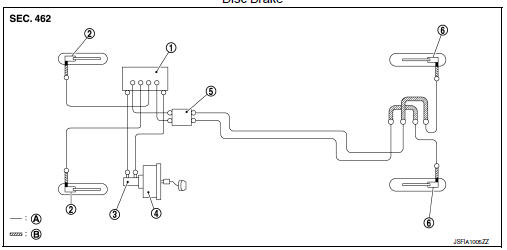
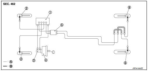
Disc Brake
- ABS actuator and electric unit (control unit)
- Front disc brake
- Master cylinder assembly
- Brake booster
- Connector
- Rear disc brake
- Brake tube
- Brake hose
 Flare nut
 Union bolt
CAUTION:
- All hoses and piping (tubes) must be free from excessive bending, twisting and pulling.
- Make sure there is no interference with other parts when turning steering wheel both clockwise and counterclockwise.
- The brake piping is an important safety part. If a brake fluid leak is detected, always disassemble the parts. Replace applicable part with a new one, if necessary.
- Do not spill or splash brake fluid on painted surfaces. Brake fluid may damage paint. If brake fluid is splashed on painted areas, wash it away with water immediately.
- Do not bend or twist brake hose sharply, or strongly pull it.
- When removing components, cover connections so that no dirt, dust, or other foreign matter gets in.
- Do not reuse drained brake fluid.
- After installation of the ABS actuator and electric unit (control unit), refill brake system with new brake fluid. Then bleed the air from the system. Refer to BR-17, "Bleeding Brake System".
FRONT : Removal and Installation
NOTE:
When removing components such as hoses, tubes/lines, etc., cap or plug openings to prevent fluid from spilling.
REMOVAL
- Remove wheels and tires using power tool. Refer to WT-47, "Removal and Installation".
- Drain brake fluid. Refer to BR-17, "Drain and Refill".
- Loosen the flare nut with suitable tool and separate the brake pipe from the hose.
CAUTION:
- Do not scratch the flare nut and the brake pipe.
- All brake hoses and pipes must be free from excessive bending, twisting and pulling.
- Remove the union bolt and the brake hose from the brake caliper assembly. Remove and discard the copper sealing washers.
CAUTION:
Do not reuse copper sealing washers.
- Remove the lock plate and remove the brake hose.
INSTALLATION
CAUTION:
Do not allow foreign matter (e.g. dust) and oils other than brake fluid to enter the reservoir tank.
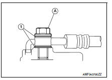
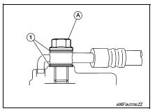
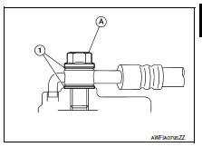
- Assemble the union bolt (A) and the copper sealing washers (1)
to the brake hose and install it as an assembly to the caliper.
Align the brake hose L-pin by aligning it with the brake caliper assembly hole, and tighten the union bolt (1) to the specified torque.
CAUTION:
Do not reuse copper sealing washers.
- Install the brake pipe to the brake hose, temporarily tighten the flare nut by hand until it does not rotate further, and secure the brake hose to the bracket with the lock plate.
CAUTION:
Check that the brake hoses and pipes are not bent or twisted.
- Tighten the flare nut to the specified torque with a flare nut torque wrench.
CAUTION:
Do not scratch the flare nut and the brake tube.
- Refill with new brake fluid and perform the air bleeding. Refer to BR-17, "Bleeding Brake System".
CAUTION:
Do not reuse drained brake fluid.
- Install the wheels and tires. Refer to WT-47, "Removal and Installation".
Rear
REAR : Exploded View
Drum Brake
- Brake tube
- Brake hose
- Lock plate
- To drum brake
- To brake pipe connector
 Front
Front
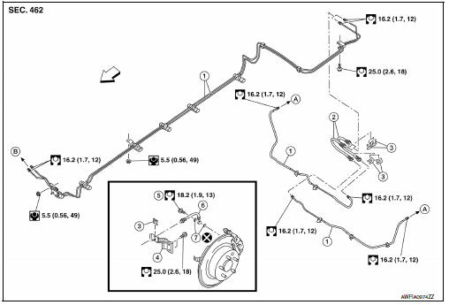
Disc Brake
- Brake tube
- Brake hose
- Lock plate
- Brake hose bracket
- Union bolt
- Rear brake hose
- Copper sealing washer
- To disc brake
- To brake pipe connector
 Front
Front
REAR : Hydraulic Piping
Drum Brake
- ABS actuator and electric unit (control unit)
- Front disc brake
- Master cylinder assembly
- Brake booster
- Connector
- Rear drum brake
- Brake tube
- Brake hose
 Flare nut
 Union bolt
Disc Brake
- ABS actuator and electric unit (control unit)
- Front disc brake
- Master cylinder assembly
- Brake booster
- Connector
- Rear disc brake
- Brake tube
- Brake hose
 Flare nut
 Union bolt
CAUTION:
- All hoses and piping (tubes) must be free from excessive bending, twisting and pulling.
- Make sure there is no interference with other parts.
- The brake piping is an important safety part. If a brake fluid leak is detected, always disassemble the parts. Replace applicable part with a new one, if necessary.
- Do not spill or splash brake fluid on painted surfaces. Brake fluid may damage paint. If brake fluid is splashed on painted areas, wash it away with water immediately.
- Do not bend or twist brake hose sharply, or strongly pull it.
- When removing components, cover connections so that no dirt, dust, or other foreign matter gets in.
- Do not reuse drained brake fluid.
- After installation of the ABS actuator and electric unit (control unit), refill brake system with new brake fluid. Then bleed the air from the system. Refer to BR-17, "Bleeding Brake System".
REAR : Removal and Installation
DRUM BRAKES
NOTE:
When removing components such as hoses, tubes/lines, etc., cap or plug openings to prevent fluid from spilling.
Removal
CAUTION:
Do not spill or splash brake fluid on painted surfaces. Brake fluid may damage paint. If brake fluid is splashed on painted areas, wash it away with water immediately.
- Remove wheels and tires using power tool. Refer to WT-47, "Removal and Installation".
- Drain brake fluid. Refer to BR-17, "Drain and Refill".
- Loosen the flare nut with suitable tool and separate the brake pipe from the brake hose.
CAUTION:
- Do not scratch the flare nut and the brake pipe.
- All brake hoses and pipes must be free from excessive bending, twisting and pulling.
- Remove the lock plate and remove the brake hose from the vehicle.
- Loosen the flare nut with a flare nut wrench and separate the brake pipe from the wheel cylinder, and remove the brake pipe.
Installation
- Connect the brake pipe to the wheel cylinder, temporarily tighten the flare nut by hand until it does not rotate further.
- Connect the brake hose to the brake pipe, temporarily tighten the flare nut by hand until it does not rotate further, and secure the brake hose to the bracket with the lock plate.
CAUTION:
Check that the brake hoses and pipes are not bent or twisted.
- Tighten the flare nut to the specified torque using suitable tool.
CAUTION:
Do not scratch the flare nut and the brake tube.
- Refill with new brake fluid and perform the air bleeding. Refer to BR-17, "Bleeding Brake System".
CAUTION:
Do not reuse drained brake fluid.
- Install the wheels and tires. Refer to WT-47, "Removal and Installation".
Disc brakes
NOTE:
When removing components such as hoses, tubes/lines, etc., cap or plug openings to prevent fluid from spilling.
Removal
- Remove the wheels and tires using power tool. Refer to WT-47, "Removal and Installation".
- Drain brake fluid. Refer to BR-17, "Drain and Refill".
- Loosen the flare nut with suitable tool and separate the brake tube from the hose.
CAUTION:
- Do not scratch the flare nut and the brake pipe.
- All brake hoses and pipes must be free from excessive bending, twisting and pulling.
- Remove the union bolt (A) and the brake hose from the brake caliper. Remove and discard the copper sealing washers (1).
CAUTION:
Do not reuse copper sealing washers.
- Remove the lock plate and remove the brake hose.
Installation
CAUTION:
Do not allow foreign matter (e.g. dust) and oils other than brake fluid to enter the reservoir tank.
Assemble the union bolt (A) and the copper sealing washers (1) to the brake hose and install it as an assembly to the brake caliper.
Align the brake hose L-pin by aligning it with the brake caliper hole, and tighten the union bolt (A) to the specified torque.
CAUTION:
Do not reuse copper sealing washers.
- Install the brake pipe to the brake hose, temporarily tighten the flare nut by hand until it does not rotate further, and attach the brake hose to the bracket with the lock plate.
CAUTION:
Check that the brake hoses and pipes are not bent or twisted.
- Tighten the flare nut to the specified torque using suitable tool.
CAUTION:
Do not scratch the flare nut and the brake pipe.
- Refill with new brake fluid and perform the air bleeding. Refer to BR-17, "Bleeding Brake System".
CAUTION:
Do not reuse drained brake fluid.
- Install the wheels and tires. Refer to WT-47, "Removal and Installation".
 Brake pedal
Exploded View
WITHOUT BRAKE PEDAL POSITION SWITCH
Snap pin
Brake pedal assembly
Brake pedal pad
Stop lamp switch
Clip
Clevis pin
Apply multi-purpose grease.
WITH BRAKE PEDAL POSI ...
 Brake master cylinder
Exploded View
Reservoir cap
Oil strainer
Reservoir tank
Cylinder body
Pin
O-ring
Grommet
Apply brake fluid
PBC (Poly Butyl Cuprysil)
grease or
silicone-based grease
Remo ...
Other materials:
Basic inspection
Diagnosis and repair workflow
Work flow
OVERALL SEQUENCE
DETAILED FLOW
1.GET INFORMATION FOR SYMPTOM
Get detailed information from the customer about the symptom (the condition
and the environment when the
incident/malfunction occurred).
>> GO TO 2
2.CONFIRM THE SYMPTOM
Try to ...
Vanity mirror lamp
Removal and installation
Caution:
Do not attempt to separate the vanity mirror lamp from the sun visor or
damage to the components
may occur.
Note:
The vanity mirror lamp is replaced as part of the sun visor. Refer to
int-40, "removal and installation".
Bulb or lens replacement
...
Exhaust valve timing control
EXHAUST VALVE TIMING CONTROL : System
Description
SYSTEM DIAGRAM
INPUT/OUTPUT SIGNAL CHART
Sensor
Input signal to ECM
ECM function
Actuator
Crankshaft position sensor (POS)
Engine speed and piston position
Exhaust valve
timing control
Exhaust valve timing ...
