Nissan Sentra B18 (2020-2025) Service Manual: B2090-14 Nats Antenna Amp.
Dtc Description
DTC Description
DTC DETECTION LOGIC
|
DTC No. |
CONSULT screen items (Trouble diagnosis content) |
DTC detecting condition |
|
|---|---|---|---|
|
B2090–14 |
NATS antenna amp. (Nissan anti-theft system antenna amplifier) |
Diagnosis condition |
Work support ‟INSIDE/OUTSIDE ANT DIAGNOSIS”: activated |
|
Signal (terminal) |
NATS antenna signal |
||
|
Threshold |
Inactive communication between NATS antenna and Intelligent Key unit |
||
|
Diagnosis delay time |
1 second or less |
||
POSSIBLE CAUSE
-
Harness or connectors
(NATS antenna circuit is open or shorted.)
-
Push-button ignition switch (NATS antenna)
-
Intelligent Key unit
FAIL-SAFE
—
Confirmation Procedure
Confirmation Procedure
-
PERFORM DTC CONFIRMATION PROCEDURE
-
 CONSULT
-
Select “INSIDE/OUTSIDE ANT DIAGNOSIS” in “Work support” mode of “HANDS FREE MODULE”.
-
Select “Self Diagnostic Result” mode of “HANDS FREE MODULE”.
-
Is the DTC detected?
YES >>Refer to DTC Diagnosis Procedure.
NO >>To check malfunction symptom before repair: Refer to Intermittent Incident.
NO >>Confirmation after repair: Inspection End.
-
Dtc Diagnosis Procedure
DTC Diagnosis Procedure
-
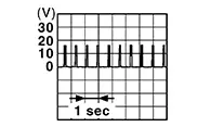
CHECK NATS ANTENNA COMMUNICATION SIGNAL
-
Check signal between push-button ignition switch harness connector and ground using an oscilloscope.
(+)
(–)
Condition
Signal
(Reference value)
Push-button ignition switch
Connector
Terminal
M25
2
Ground
Intelligent Key battery is removed and brake pedal is depressed
When a registered Intelligent Key backside is contacted to push-button ignition switch
0 V
Other than above
3
When a registered Intelligent Key backside is contacted to push-button ignition switch
0 V
Other than above
Is the inspection result normal?
YES >>GO TO 3.
NO >>GO TO 2.
-
-
CHECK NATS ANTENNA COMMUNICATION SIGNAL CIRCUIT
-
-
Ignition switch OFF.
-
Disconnect Intelligent Key unit connector and push-button ignition switch connector.
-
Check continuity between push-button ignition switch harness connector and Intelligent Key unit harness connector.
Push-button ignition switch
Intelligent Key unit
Continuity
Connector
Terminal
Connector
Terminal
M25
2
M155
19
Yes
3
20
-
Check continuity between push-button ignition switch harness connector and ground.
Push-button ignition switch
—
Continuity
Connector
Terminal
M25
2
Ground
No
3
-
Is the inspection result normal?
YES >>GO TO 3.
NO >>Repair or replace harness.
-
-
REPLACE PUSH-BUTTON IGNITION SWITCH
-
Replace push-button ignition switch. Refer to Removal and Installation.
Is the inspection result normal?
YES >>Inspection End.
NO >>GO TO 4.
-
-
REPLACE INTELLIGENT KEY UNIT
-
Replace Intelligent Key unit. Refer to Removal and Installation.
Inspection End.
-
Other materials:
Stop Lamp
Component Inspection
Component Inspection
CHECK STOP LAMP 1
Ignition switch OFF.
Disconnect rear combination lamp (body side) connector
and high-mounted stop lamp connector. ...
Siri Eyes Free
Apple Siri Eyes Free personal assistant can be accessed directly from the Nissan
Sentra, allowing drivers to use Siri with reduced distraction. Siri Eyes Free operates
in a dedicated voice-only mode, enabling hands-free interaction while keeping your
attention on the road. After pairing a comp ...
Sunload Sensor
Diagnosis Procedure
Diagnosis Procedure
CHECK SUNLOAD SENSOR SIGNAL
Ignition switch ON.
Check voltage between A/C auto amp. harness connector.
...