Nissan Sentra B18 (2020-2025) Service Manual: Remote Keyless Entry Function
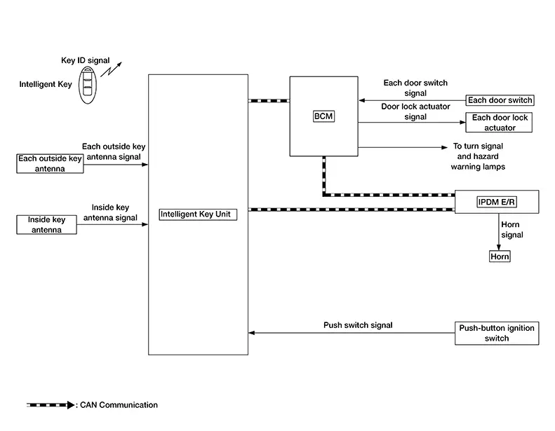
System Diagram
System Diagram
System Description
System Description
The Intelligent Key has the same functions as the remote control entry system. Therefore, it can be used in the same manner as the remote controller by operating the door lock/unlock button.
OPERATION
Remote keyless entry system controls operation of the following items:
-
Door lock/unlock function
-
Auto door lock function
-
Hazard and horn reminder function
INPUT SIGNAL AND OUTPUT SIGNAL
|
Signal name |
Input |
Output |
Description |
|---|---|---|---|
|
Key ID signal |
Intelligent Key |
Intelligent Key unit |
The Intelligent Key unit receives key ID signal inputs and activates the actuators accordingly. |
|
Outside key antenna signal |
Outside key antenna |
Intelligent Key unit |
The Intelligent Key unit receives outside key antenna signals inputs and activates the actuators accordingly. |
|
Inside key antenna signal |
Inside key antenna |
Intelligent Key unit |
The Intelligent Key unit receives inside key antenna signals inputs and activates the actuators accordingly. |
|
Push switch signal |
Push-button ignition switch |
Intelligent Key unit |
The Intelligent Key unit receives push switch signal inputs and activates the actuators accordingly. |
|
Door switch signal |
Door switch |
BCM |
The BCM receives door switch signals inputs and activates the actuators accordingly. |
OPERATION AREA
The remote keyless entry operating range is approximately 33 ft (10 m) from the Nissan Sentra vehicle.
DOOR LOCK/UNLOCK FUNCTION
-
When door lock/unlock button of the Intelligent Key is pressed, lock signal or unlock signal transmitted from Intelligent Key to Intelligent Key unit.
-
When Intelligent Key unit receives the door lock/unlock signal, it operates all door lock actuators, blinks the hazard lamp (lock: 2 time, unlock: 1 times) and horn chirp signal to IPDM E/R at the same time as a reminder.
-
IPDM E/R honks horn (lock: 1 time) as a reminder.
OPERATION CONDITION
If the following condition are satisfied, remote keyless entry operation is performed when the Intelligent Key is operated:
|
Remote controller operation |
Operation condition |
|---|---|
|
Lock |
|
|
Unlock |
Panic alarm is not activated. |
AUTO DOOR LOCK FUNCTION
After door is unlocked by Intelligent Key button operation and if 30 seconds or more passes without performing the following operation, all doors are locked. However, operation check function does not activate:
|
Operating condition |
|
How To Change Auto Door Lock Operation Mode.
 CONSULT
Auto door lock mode can be changed.
Refer to CONSULT Function (BCM - INTELLIGENT KEY).
HAZARD AND HORN REMINDER FUNCTION
When doors are locked or unlocked by Intelligent Key, BCM blinks hazard warning lamps as a reminder.
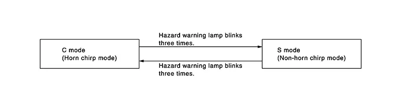
The hazard and horn reminder has a horn chirp mode (C mode) and a non-horn chirp mode (S mode).
Operating Function of Hazard and Horn Reminder
|
C mode |
S mode |
|||
|---|---|---|---|---|
|
Intelligent Key operation |
Lock |
Unlock |
Lock |
Unlock |
|
Hazard warning lamp blinks |
Twice |
Once |
Twice |
— |
|
Horn sound |
Once |
— |
— |
— |
Hazard and horn reminder does not operate in the following conditions:
-
Ignition switch is ON.
-
Door is open (only lock operation).
How to Change Hazard and Horn Reminder Mode
 CONSULT
Hazard and horn reminder operation mode can be changed.
Refer to CONSULT Function (BCM - INTELLIGENT KEY).
 CONSULT
When LOCK and UNLOCK signals are sent from the Intelligent Key for more than 2 seconds at the same time, the hazard and horn reminder mode is changed and hazard warning lamp blinks and horn sounds as per the following items:
LIST OF OPERATION RELATED PARTS
Parts marked with Ă— are the parts related to operation.
|
Function |
Intelligent Key |
Door switch |
Door lock actuator |
Push-button ignition switch |
CAN communication system |
BCM |
IPDM E/R |
Horn |
Combination meter |
Hazard warning lamp |
Trunk lid opener assembly (ajar switch) |
|---|---|---|---|---|---|---|---|---|---|---|---|
|
Door lock/unlock function |
Ă— |
Ă— |
Ă— |
Ă— |
|||||||
|
Auto door lock function |
Ă— |
Ă— |
Ă— |
Ă— |
Ă— |
||||||
|
Hazard and horn reminder function |
Ă— |
Ă— |
Ă— |
Ă— |
Ă— |
Ă— |
Other materials:
Oil Seal
Valve Oil Seal
Removal and Installation
Removal and Installation
REMOVAL
Remove
camshafts. Refer to Removal and Installation.
Remove
valve lifters. Refer to Exploded View.
Rotate
crankshaft and set piston whose valve oil seal is to be removed to
TDC. This will prev ...
U2141 Mac Comm Error (tcm)
Dtc Description
DTC Description
DTC DETECTION LOGIC
DTC No.
CONSULT screen terms
(Trouble diagnosis
content)
DTC detection condition
...
Air Breather Hose
Exploded View
Exploded View
1.
Air breather hose
2.
Transaxle assembly
A.
...