Nissan Sentra B18 (2020-2025) Service Manual: Oil Seal
Valve Oil Seal
Removal and Installation
Removal and Installation
REMOVAL
Remove camshafts. Refer to Removal and Installation.
Remove valve lifters. Refer to Exploded View.
Rotate crankshaft and set piston whose valve oil seal is to be removed to TDC. This will prevent valve from dropping into cylinder.
CAUTION:
When rotating crankshaft, be careful to avoid scarring front cover with timing chain.
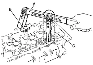
Compress
the valve spring with suitable tool (A/B/C) and remove the valve
collet with a suitable magnetic tool.
CAUTION:
-
Do not damage valve lifter holes.
-
The center of suitable tool (A) and valve spring retainer (1) must be aligned.
Remove valve spring retainer and valve spring (with valve spring seat).
CAUTION:
Do not remove valve spring seat from valve spring.
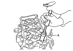
Remove
valve oil seal with suitable tool (A).
INSTALLATION
Apply new engine oil to valve oil seal joint surface and seal lip.
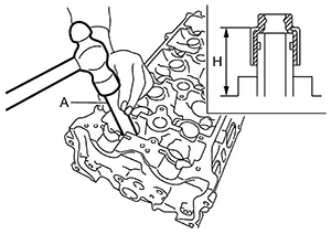
Press in
valve oil seal using suitable tool (A) to the specified height
(H).
|
Height (H) |
: 15.1 - 15.7 mm (0.594 - 0.618 in) |
Installation of the remaining components is in the reverse order of removal.
Front Oil Seal
Removal and Installation
Removal and Installation
REMOVAL
Remove the front fender protector (RH). Refer to Removal and Installation.
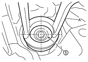
Remove
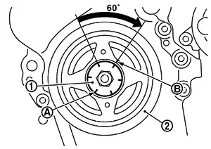
crankshaft pulley using the following procedure: Secure crankshaft pulley (1) with a
suitable tool (A) and loosen crankshaft pulley bolt.
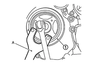
CAUTION:
Do not remove the crankshaft pulley bolt as it is used as a supporting point for a suitable puller.
Attach a suitable puller (A) in the threaded hole on crankshaft pulley (1) and remove crankshaft pulley.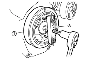
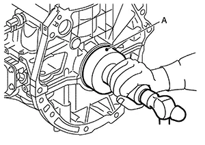
Remove front oil seal with a suitable tool.
CAUTION:
-
Do not damage front cover and crankshaft.
-
Do not reuse front oil seal.
INSTALLATION
Apply new engine oil to new front oil seal joint surface and seal lip.
CAUTION:
Do not reuse front oil seal.
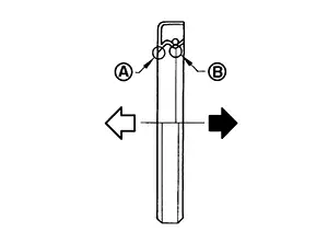
Install
front oil seal so that each seal lip is oriented as shown.
|
(A) |
: Dust seal lip |
|
(B) |
: Oil seal lip |
|
|
: Engine outside |
|
|
: Engine inside |

-
Press-fit front oil seal using a suitable drift with outer diameter 57 mm (2.24 in) and inner diameter 45 mm (1.77 in).
CAUTION:
-
Do not damage front cover or crankshaft.
-
Press-fit front oil seal straight to avoid causing burrs or tilting.

Front oil seal (2) should be installed within the range shown from the front face (A) of the front cover (1).
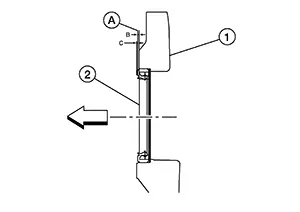
Dimension (B)
: 0.3 mm (0.012 in)
Dimension (C)
: 0.5 mm (0.020 in)

: Engine front
-
Install crankshaft pulley using the following procedure: When inserting crankshaft pulley with a suitable tool, tap on its center portion (not circumference).
CAUTION:
Do not damage front oil seal lip portion.
Secure crankshaft pulley (1) with a suitable tool (A). Apply
new engine oil to thread and seat surfaces of crankshaft pulley
bolt. Tighten crankshaft pulley bolt to
the specified torque. |
Crankshaft pulley bolt |
: 29.4 N·m (3.0 kg-m, 22 ft-lb) |
 Tighten crankshaft pulley bolt to
the specified angle using Tool.
Tighten crankshaft pulley bolt to
the specified angle using Tool.
-
Check the tightening angle with movement of one angle mark.
CAUTION:
Check and confirm the tightening angle using Tool. Avoid judgement by visual inspection without Tool.
Tool number
: KV10112100 (BT-8653-A)
Tightening angle
: 60° - 66°
Installation of the remaining components is in the reverse order of removal.
Rear Oil Seal
Removal and Installation
Removal and Installation
REMOVAL
Remove the drive plate or flywheel. Refer to Removal and Installation (CVT models) or Removal and Installation (M/T models).
Remove rear oil seal with a suitable tool.
CAUTION:
-
Do not damage crankshaft or cylinder block.
-
Do not reuse rear oil seal.
INSTALLATION
Install rear oil seal so that each seal lip is oriented as shown.
CAUTION:
Do not reuse rear oil seal.
|
(A) |
: Dust seal lip |
|
(B) |
: Oil seal lip |
|
|
: Engine outside |
|
|
: Engine inside |
-
Press-fit rear oil seal with a suitable drift (A) outer diameter 115 mm (4.53 in) and inner diameter 90 mm (3.54 in).
CAUTION:
-
Do not damage crankshaft or cylinder block.
-
Press-fit rear oil seal straight to avoid causing burrs or tilting.
-
Do not touch grease applied onto oil seal lip.
-
-
Press in rear oil seal (1) to the position as shown.
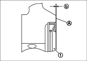
Dimension (b)
: -0.3 - 0.05 mm (-0.012 in - 0.020 in)
(A)
: Rear end surface of cylinder block
Installation of the remaining components is in the reverse order of removal.
Other materials:
Intelligent Key Unit. Removal and Installation
Removal and Installation
Removal and Installation
REMOVAL
CAUTION:
Be sure to perform “ADDITIONAL
SERVICE WHEN REPLACING INTELLIGENT KEY UNIT” when replacing
Intelligent Key unit. Refer to Work Procedure.
Remove
instrument panel assembly. Refer to Removal and ...
Side Radar Right (side Radar Rh)
C1e80-44 Control Unit
Dtc Description
DTC Description
DTC DETECTION LOGIC
DTC No.
CONSULT screen terms
(Trouble diagnosis
content)
DTC detecti ...
Maintenance precautions
When performing any inspection, servicing, or maintenance work on your Nissan
Sentra, always exercise extreme care to avoid serious personal injury or accidental
damage to the vehicle. Routine maintenance plays an important role in the long-term
reliability, safety, and performance of the Niss ...