Nissan Sentra B18 (2020-2025) Service Manual: Drive Plate
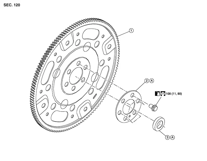
Exploded View
Exploded View
|
1. |
Drive plate |
2. |
Drive plate reinforcement |
3. |
: Pilot converter |
|
A. |
Refer to Removal and Installation. |
Removal and Installation
Removal and Installation
REMOVAL
Remove the engine and the transaxle assembly from the vehicle, and separate the transaxle from the engine. Refer to Removal and Installation.
Remove the drive plate using the
following procedure:
Secure crankshaft pulley (1) with a
suitable tool (A).
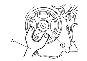 Loosen drive plate bolts and remove
drive plate and drive plate reinforcement.
Loosen drive plate bolts and remove
drive plate and drive plate reinforcement.
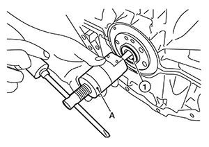
Remove the pilot converter (1)
from the rear end of the crankshaft. Use a suitable tool (A) if
necessary.
INSTALLATION
Install
drive plate (1), drive plate reinforcement (2) and pilot converter
(3) as shown. 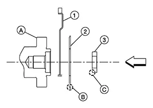
-
Using a suitable drift of 33 mm (1.30 in) in diameter, press fit the pilot converter into the end of the crankshaft (A) until it stops.
|
(B) |
: Rounded |
|
(C) |
: Chamfered |
|
: Engine front |
Hand tighten drive plate bolts in a diagonal order over several steps.
With crankshaft pulley secured, tighten drive plate bolts in a diagonal order over several steps.
Installation of the remaining components is in the reverse order of removal.
Inspection
Inspection
DRIVE PLATE DEFLECTION
Appearance of Drive Plate
-
Check ring gear for dents, scratches or chipper teeth. If any exist, replace drive plate.
DRIVE PLATE LATERAL RUN-OUT
-
Install drive plate to crank shaft and measure lateral run-out with suitable tool (A) at the locations (B) shown.
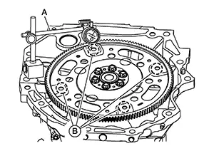
Standard
: 0.35 mm (0.014 in) or less
-
If the measurement value is outside the reference value, replace drive plate.
Other materials:
U2148-87 Can Comm Err (brake Control Unit)
Dtc Description
DTC Description
DESCRIPTION
CAN (Controller Area Network) is a serial communication
line for real time applications. It is an on-Nissan Sentra vehicle multiplex communication
line with high data communication speed and excellent error detection
ability. Modern Nissan ...
Air Breather Hose
Exploded View
Exploded View
1.
Air breather hose
2.
Transaxle assembly
A.
...
Exterior. Precaution. Precautions
Precautions
Precaution for Supplemental Restraint System (srs) "air Bag" and "seat Belt Pre-Tensioner"
Precaution for Supplemental Restraint System (SRS) "AIR BAG" and "SEAT BELT PRE-TENSIONER"
The Supplemental Restraint System such as
ÔÇťAIR BAGÔÇŁ and ÔÇťSEAT BELT PRE-T ...