Nissan Sentra B18 (2020-2025) Service Manual: Flywheel
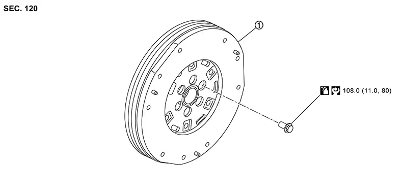
Exploded View
Exploded View
|
1. |
Flywheel |
Removal and Installation
Removal and Installation
REMOVAL
Remove the engine and the transaxle assembly from the vehicle, and separate the transaxle from the engine. Refer to Removal and Installation.
Remove the clutch disc and clutch cover. Refer to Exploded View.
Remove flywheel bolts in diagonal order with power tool.
CAUTION:
-
Any dropped flywheel shall not be used.
-
Do not touch flywheel with bare hands. Always use urethane coating gloves or skin gloves when removing these parts.
-
Do not use torn glove.
-
Do not disassemble.

Check for deformation or damage of flywheel.
INSTALLATION
Installation is in the reverse order of removal.
CAUTION:
Do not damage or scratch and contact surface for clutch disc of flywheel.
Note:
Before installing flywheel, clean the flywheel to remove grease and dust caused by abrasion.
Inspection
Inspection
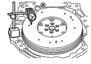
FLYWHEEL DEFLECTION
-
Measure the deflection of flywheel contact surface to torque with a suitable tool (A).
-
Measure the deflection at 210 mm (8.27 in) diameter.
Limit
: 0.45 mm (0.0177 in) or less.
-
If measured value is out of the standard, replace flywheel.
-
If a trace of burn or discoloration is found on the surface, repair it with sandpaper.
MOVEMENT AMOUNT OF FLYWHEEL
CAUTION:
Never disassemble double mass flywheel.
Movement Amount of Thrust (Fore-and-Aft) Direction
-
Measure the movement amount of thrust (fore-and-aft) direction when 100 N (10.2 kg, 22 lb) force is added at the portion of 125 mm (4.92 in) radius from the center of flywheel.
Standard
: 3.6 mm (0.1417 in) or less
-
If measured value is out of the standard, replace flywheel.
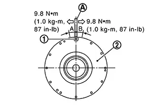
Movement Amount in Radial (Rotation) Direction
Check the movement amount of radial (rotation) direction according to the following procedure:
-
Install clutch cover mounting bolt (1) to clutch cover mounting hole, and place a torque wrench (A) on the extended line of the flywheel (2) center line.
-
Tighten bolt at a force of 9.8 N·m (1.0 kg-m, 87 in-lb) to keep it from loosening.
-
-
Put a mating mark on circumferences of the two flywheel masses without applying any load (Measurement standard points).
-
Apply a force of 9.8 N·m (1.0 kg-m, 87 in-lb) in each direction, and mark the movement amount on the mass on the transaxle side.
-
Measure the dimensions of movement amounts “A” and “B” on circumference of the flywheel on the transaxle side.
Limit
: 66.7 mm (2.626 in) or less.
-
If measured value is out of the standard, replace flywheel.
-
Other materials:
B24d4-08 A/c Control Comm
Dtc Description
DTC Description
DTC DETECTION LOGIC
DTC No.
CONSULT screen terms
(Trouble diagnosis content)
DTC detection condition
...
U2140-87 Can Comm Err (ecm)
Dtc Description
DTC Description
DESCRIPTION
CAN (Controller Area Network) is a serial communication
line for real time applications. It is an on-Nissan Sentra vehicle multiplex communication
line with high data communication speed and excellent error detection
ability. Modern Nissan ...
Diagnosis System (intelligent Key). Intelligent Key
Intelligent Key
Consult Function (intelligent Key Unit)
CONSULT Function (INTELLIGENT KEY UNIT)
SELF DIAGNOSTIC RESULT
Refer to DTC Index.
DATA MONITOR
Note:
The following table includes information (items)
inapplicable to this Nissan Sentra vehicle. For information (items) appl ...