Nissan Sentra B18 (2020-2025) Service Manual: Cylinder Head
Exploded View
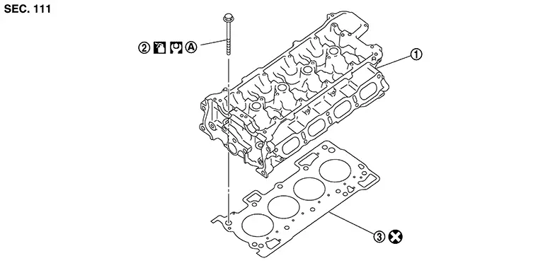
Exploded View
REMOVAL
|
1. |
Cylinder head assembly |
2. |
Cylinder head bolt |
3. |
Cylinder head gasket |
|
A. |
Refer to Removal and Installation. |
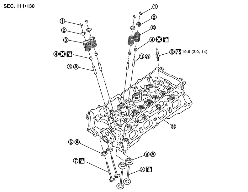
DISASSEMBLY
|
1. |
Valve collet |
2. |
Valve spring retainer |
3. |
Valve spring (EXH) |
|
4. |
Valve oil seal |
5. |
Valve guide (EXH) |
6. |
Valve seat (EXH) |
|
7. |
Valve (EXH) |
8. |
Valve (INT) |
9. |
Valve seat (INT) |
|
10. |
Cylinder head |
11. |
Valve guide (INT) |
12. |
Spark plug |
|
13. |
Valve spring (INT) |
A. |
Refer to Disassembly and Assembly. |
Removal and Installation
Removal and Installation
REMOVAL
Remove the camshafts. Refer to Removal and Installation.
Remove the EGR inlet tube heat shield. Refer to Exploded View.
Remove the bolts securing the EGR inlet tube to the exhaust manifold. Refer to Exploded View.
Disconnect the harness connector from the air fuel ratio (A/F) sensor 1.
Disengage the air fuel ratio (A/F) sensor 1 harness from the harness retainer on the exhaust manifold cover.
Remove exhaust manifold cover. Refer to Exploded View.
Remove exhaust manifold stay. Refer to Exploded View.
Loosen
exhaust manifold nuts in reverse of the sequence shown and remove
exhaust manifold.
CAUTION:
Do not reuse exhaust manifold nuts.
Remove exhaust manifold gasket.
CAUTION:
-
Cover engine openings to avoid entry of foreign materials.
-
Do not reuse exhaust manifold gasket.
Remove the high pressure fuel rail insulator. Refer to Exploded View.
Disconnect the harness connector from the fuel rail pressure sensor.
Loosen high
pressure fuel rail nuts and bolts in reverse of the sequence shown
and remove the high pressure fuel rail.
CAUTION:
-
When removing, be careful to avoid any interference with fuel injector.
-
Use a shop cloth to absorb any fuel that leaks from high pressure fuel rail.
If fuel injectors remain in cylinder head after removing high pressure fuel rail, remove the fuel injectors using the following procedure:
CAUTION:
-
Be careful with remaining fuel that may go out from high pressure fuel rail.
-
Be careful not to damage injector nozzles during removal.
-
Do not bump or drop fuel injector.
-
Do not disassemble fuel injector.
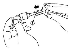
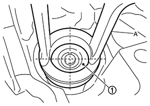
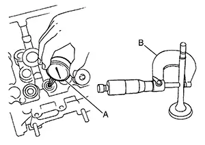
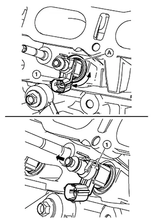 Rotate fuel injector assembly (1)
back and forth to allow suitable lubricant to seep into
bore.
Pull
straight out on fuel injector assembly to remove from cylinder
head.
Rotate fuel injector assembly (1)
back and forth to allow suitable lubricant to seep into
bore.
Pull
straight out on fuel injector assembly to remove from cylinder
head.
Remove O-ring, backup ring and injector holder from fuel injector. Refer to Exploded View.
CAUTION:
Do not reuse O-ring, backup ring or injector holder.
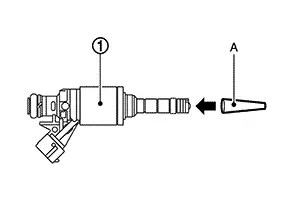
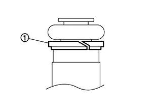
Cut seal
ring (1) while pinching it.
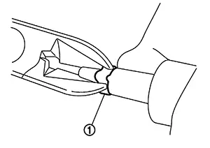
CAUTION:
-
Do not scratch fuel injector when removing seal ring.
-
Do not reuse seal ring.
Disconnect the harness connector from the engine coolant temperature sensor. Refer to Exploded View.
Remove the water hoses from the EGR cooler. Refer to Exploded View.
Remove bolts and remove the EGR cooler (if necessary). Refer to Exploded View.
CAUTION:
Do not reuse EGR cooler gasket.
Remove bolts and remove the EGR cooler bracket (if necessary). Refer to Exploded View.
Remove the bolt and remove the ground cable from the cylinder head.
Remove the water outlet (if necessary). Refer to Exploded View.
Loosen
cylinder head bolts in reverse of the sequence shown and remove the
cylinder head.
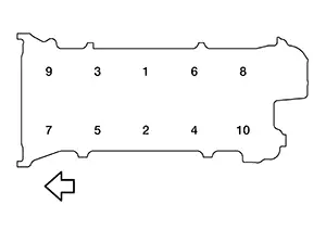
|
|
: Engine front |
Remove cylinder head gasket.
CAUTION:
Do not reuse cylinder head gasket.
INSTALLATION
Install cylinder head gasket.
CAUTION:
Do not reuse cylinder head gasket.
Install cylinder head and tighten cylinder head bolts using the following procedure:
CAUTION:
If cylinder head bolts are reused, check their outer diameters before installation. Refer to Inspection.
Tighten all cylinder head bolts to the specified torque in the sequence shown.
|
Cylinder head bolts |
: 40 N┬Ęm (4.1 kg-m, 30 ft-lb) |
|
|
: Engine front |
CAUTION:
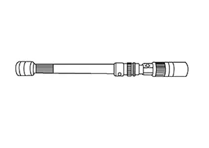
Check and confirm the tightening angle by using a Tool (A) or protractor. Do not judge by visual inspection without the Tool.
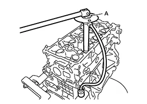
|
Tool number (A) |
: KV10112100 (BT-8653-A) |
|
Tightening angle |
: 100┬░ |
CAUTION:
Check and confirm the tightening angle by using a Tool (A) or protractor. Do not judge by visual inspection without the Tool.
|
Tool number (A) |
: KV10112100 (BT-8653-A) |
|
Tightening angle |
: 100┬░ |
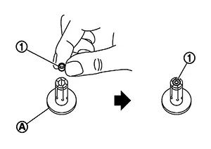
Install seal ring to fuel injector using the following procedure:
CAUTION:
-
Handle seal ring with bare hands. Do not wear gloves.
-
Do not apply engine oil to seal ring.
-
Do not clean seal ring with solvent.
|
Tool number (A) |
: KV10119720 (NI-50364) |
|
Tool number (A) |
: KV10119730 (NI-50364) |
CAUTION:
Be careful that seal ring does not exceed the groove portion of fuel injector.
Insert Tool (A) to fuel injector and rotate clockwise and counterclockwise by 90┬░ while pressing seal ring to fit it.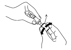 Note:
Note: 
This is done to correct any elongation of the seal ring caused by installation and for preventing sticking when inserting fuel injector into cylinder head.
|
Tool number (A) |
: KV10119710 (NI-50364) |
Install O-ring and backup ring to fuel injector.
CAUTION:
-
Do not reuse O-ring.
-
Handle O-ring with bare hands. Do not wear gloves.
-
Lubricate O-ring with new engine oil.
-
Do not clean O-ring with solvent.
-
Check that O-ring and its mating part are free of foreign material.
-
When installing O-ring , be careful not to scratch it with tool or fingernails. Also be careful not to twist or stretch O-ring . If O-ring was stretched while it was being attached, do not insert it quickly into high pressure fuel rail.
-
Insert new O-ring straight into high pressure fuel rail. Do not decenter or twist it.
-
Always install the back up ring (1) in the right direction as instructed.
Install the
fuel injectors to the high pressure fuel rail using the following
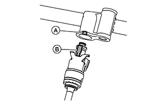
procedure: Install the injector holder (1) onto
the fuel injector (2). 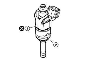
CAUTION:
-
Do not reuse injector holder.
-
Be careful to keep injector holder from interfering with O-ring. If interference occurs, replace O-ring.
-
Insert it while matching it to the axial center.
-
Insert so that tab (B) of injector holder is aligned to cutout (A) of high pressure fuel rail.
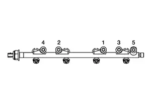
Install
high pressure fuel rail and fuel injector assembly to cylinder head
and tighten nuts and bolts to the specified torque in the sequence
shown.
|
Step 1 |
: 10.0 N┬Ęm (1.0 kg-m, 89 in-lb) |
|
Step 2 |
: 25 N┬Ęm (2.6 kg-m, 18 ft-lb) |
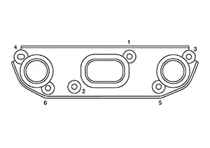
Install exhaust manifold gasket to cylinder head.
CAUTION:
Do not reuse exhaust manifold gasket.
Install
exhaust manifold and tighten exhaust manifold nuts to the specified
torque in the sequence shown.
CAUTION:
Do not reuse exhaust manifold nuts.
Note:
Repeat tightening sequence to ensure exhaust manifold nuts are tightened to the specified torque.
|
Exhaust manifold nuts |
: 33.4 N┬Ęm (3.4 kg-m, 25 ft-lb) |
Installation of the remaining components is in the reverse order of removal.
Disassembly and Assembly
Disassembly and Assembly
DISASSEMBLY
Remove spark plug with Tool.
|
Tool number |
:ŌĆāŌĆöŌĆā(NI-48891) |
Remove valve lifter.
-
Identify installation positions, and store them without mixing them up.
Compress
the valve spring with suitable tool (A/B/C) and remove the valve
collet with a suitable magnetic tool.
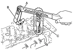
CAUTION:
-
Be careful not to damage valve lifter holes.
-
The center of the suitable tool (A) and valve spring retainer (1) must be aligned.
Remove valve spring retainer and valve spring (with valve spring seat).
CAUTION:
Do not remove valve spring seat from valve spring.
Push valve into combustion chamber side and remove valve.
-
Identify installation positions, and store them without mixing them up.
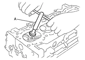
Remove
valve oil seal with suitable tool (A).
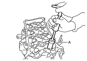
When valve seat must be replaced.
-
Bore out old valve seat until it collapses. Boring should not continue beyond the bottom face of the valve seat recess in cylinder head. Set the machine depth stop to ensure this. Refer to Cylinder Head.
CAUTION:
Do not bore excessively to prevent cylinder head from being damaged.
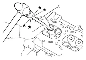
Drive out
valve guide with a hammer and suitable tool (A).
ASSEMBLY
When valve guide is removed, install it.
CAUTION:
Replace with oversize [0.2 mm (0.008 in)] valve guide.
Ream cylinder head valve guide hole with a suitable tool (A).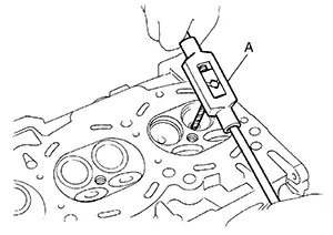
|
For service parts: Oversize [0.2 mm (0.008 in)] |
Refer to Cylinder Head. |
|
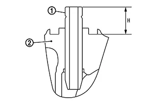
|
Projection (H) |
: Refer to Cylinder Head. |
|
|
(2) |
: Cylinder head |
|
Standard |
: Refer to Cylinder Head. |
When valve seat is removed, install it.
CAUTION:
Replace with oversize [0.5 mm (0.020 in)] valve seat.
Ream cylinder head (1) recess diameter for service valve seat (2).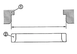
|
For service parts: Oversize [0.5 mm (0.020 in)] |
Refer to Cylinder Head. |
|
-
Be sure to ream in circles concentric to the valve guide center.
This will enable valve seat to fit correctly.
CAUTION:
When using suitable tool, firmly grip the suitable tool handle with both hands. Then, press on the contacting surface all around the circumference to cut in a single drive. Improper pressure on with the cutter or cutting many different times may result in stage valve seat.
Using compound, grind to adjust valve fitting. Check again for normal contact. Refer to Inspection.Install
valve oil seal using suitable tool (A) to the specified height
(H).
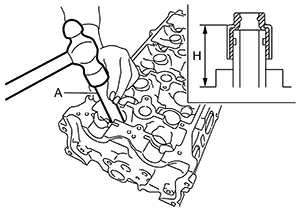 Note:
Note:
Dimension is height that measured before installing valve spring (with valve spring seat).
|
Height (H) |
: 15.1 - 15.7 mm (0.594 - 0.618 in) |
Install valve.
-
Install larger diameter to intake side.
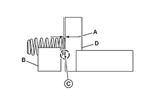
Install valve spring (with valve spring seat).
-
Install smaller pitch (valve spring seat side) to cylinder head side (B).
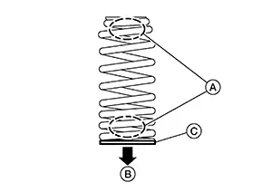
CAUTION:
Do not remove valve spring seat (C) from valve spring.
-
Confirm identification color (A) of valve spring.
Intake
: Yellow
Exhaust
: None
Install valve spring retainer.
Install valve collet.
-
Compress the valve spring with suitable tool (A/B/C) and install the valve collet with a suitable magnetic tool.
CAUTION:
-
Be careful not to damage valve lifter holes.
-
The center of the suitable tool (A) and valve spring retainer (1) must be aligned.
-
-
Tap valve stem edge lightly with a plastic hammer after installation to check its installed condition.
Install valve lifter.
-
Install it in the original position.
Install
spark plug with Tool.
|
Tool number |
:ŌĆāŌĆöŌĆā(NI-48891) |
Inspection
Inspection
INSPECTION AFTER REMOVAL
Cylinder Head Bolts Outer Diameter
-
Cylinder head bolts are tightened by plastic zone tightening method. Whenever the size difference between (A) and (B) exceeds the limit, replace them with a new one.
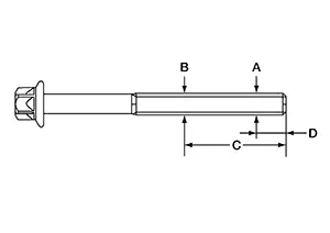
Limit [(A) ŌĆō (B)]
: 0.15 mm (0.0059 in)
Dimension (C)
: 45 mm (1.77 in)
Dimension (D)
: 11 mm (0.43 in)
-
If reduction of outer diameter appears in a position other than (B), use it as (B) point.
Cylinder Head Distortion
Note:
When performing this inspection, cylinder block distortion should be also checked. Refer to Inspection.
Wipe off engine oil and remove water scale (like deposit), gasket, sealant, carbon, etc. with a suitable tool.
CAUTION:
Do not allow gasket debris to enter passages for engine oil or water.
At each of
several locations on bottom surface of cylinder head, measure the
distortion in six directions using suitable tool (A) and suitable
tool (B).
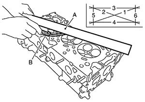
|
Limit |
: Refer to Cylinder Head. |
-
If it exceeds the limit, replace cylinder head.
INSPECTION AFTER DISASSEMBLY
VALVE DIMENSIONS
-
Check the dimensions of each valve. For the dimensions, refer to Cylinder Head.
-
If dimensions are out of the standard, replace valve and check valve seat contact. Refer to "VALVE SEAT CONTACT".
VALVE GUIDE CLEARANCE
Valve Stem Diameter
-
Measure the diameter of valve stem with a suitable tool (B).
Standard
: Refer to Cylinder Head.
Valve Guide Inner Diameter
-
Measure the inner diameter of valve guide with a suitable tool (A).
Standard
: Refer to Cylinder Head.
Valve Guide Clearance
-
(Valve guide clearance) = (Valve guide inner diameter) ŌĆō (Valve stem diameter)
Standard and Limit
: Refer to Cylinder Head.
-
If the calculated value exceeds the limit, replace valve and/or valve guide. When valve guide must be replaced. Refer to Disassembly and Assembly.
VALVE SEAT CONTACT
-
After confirming that the dimensions of valve guides and valves are within the specifications, perform this procedure.
-
Apply prussian blue (or white lead) onto contacting surface of valve seat to check the condition of the valve contact on the surface.
-
Check if the contact area band is continuous all around the circumference.
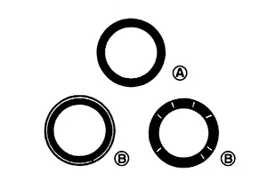
(A)
: OK
-
If not, grind to adjust valve fitting and check again. If the contacting surface still has ŌĆ£NGŌĆØ conditions (B) even after the recheck, replace valve seat. Refer to Disassembly and Assembly.
VALVE SPRING SQUARENESS
-
Set a suitable tool (D) along the side of valve spring and rotate spring. Measure the maximum clearance (A) between the top of spring and suitable tool.
(B)
: Suitable tool
(C)
: Contact area
Limit
: Refer to Cylinder Head.
-
If it exceeds the limit, replace valve spring.
VALVE SPRING DIMENSIONS AND VALVE SPRING PRESSURE LOAD
-
Check valve spring pressure (A) with valve spring seat installed at the specified spring height.
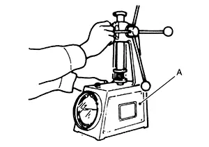
CAUTION:
Do not remove valve spring seat from valve spring.
Note:
Before measuring valve spring pressure, compress each spring to specified solid height for intake and exhaust valve springs.
Valve spring (EXH)
: 28.4 mm (1.118 in)
Valve spring (INT)
: 26.77 mm (1.0539 in)
Standard
: Refer to Cylinder Head.
-
If the installation load or load with valve open is out of the standard, replace valve spring (with valve spring seat).
INSPECTION AFTER INSTALLATION
Inspection for Leakage
The following are procedures for checking fluids leakage, lubricates leakage, and exhaust gases leakage.
-
Before starting engine, check oil/fluid levels including engine coolant and engine oil. If less than required quantity, fill to the specified level. Refer to Fluids and Lubricants.
-
Use procedure below to check for fuel leakage.
-
Place ignition switch in the ŌĆ£ONŌĆØ position (with engine stopped). With fuel pressure applied to fuel piping, check for fuel leakage at connection points.
-
Start engine. With engine speed increased, check again for fuel leakage at connection points.
-
-
Run engine to check for unusual noise and vibration.
Note:
If hydraulic pressure inside timing chain tensioner drops after removal/installation, slack in guide may generate a pounding noise during and just after the engine start. However, this does not indicate an unusualness. Noise will stop after hydraulic pressure rises.
-
Warm up engine thoroughly to check there is no leakage of fuel, or any oil/fluids including engine oil and engine coolant.
-
Bleed air from lines and hoses of applicable lines, such as in cooling system.
-
After cooling down engine, again check oil/fluid levels including engine oil and engine coolant. Refill to the specified level, if necessary.
Summary of the inspection items: Items
Before starting engine
Engine running
After engine stopped
Engine coolant
Level
Leakage
Level
Engine oil
Level
Leakage
Level
Transmission / transaxle fluid
AT & CVT Models
Leakage
Level / Leakage
Leakage
MT Models
Level / Leakage
Leakage
Level / Leakage
Other oils and fluids*
Level
Leakage
Level
Fuel
Leakage
Leakage
Leakage
Exhaust gases
ŌĆö
Leakage
ŌĆö
*: Power steering fluid, brake fluid, etc.
Other materials:
LATCH (Lower Anchors and Tethers for CHildren) system
LATCH system lower anchor locations
Your Nissan Sentra is equipped with dedicated anchor points designed for use
with LATCH systemŌĆōcompatible child restraints. This system may also be referred
to as ISOFIX or ISOFIX-compatible. When using the LATCH system, a vehicle seat belt
is not req ...
Rear Window Glass
Exploded View
Exploded View
1.
Spacer
2.
Rear window glass
3.
Adhesive ...
P0719 Brake Pedal Switch B
Dtc Description
DTC Description
DTC DETECTION LOGIC
DTC
CONSULT screen terms
(Trouble diagnosis
content)
DTC detection
condition
...