Nissan Sentra B18 (2020-2025) Service Manual: Camshaft
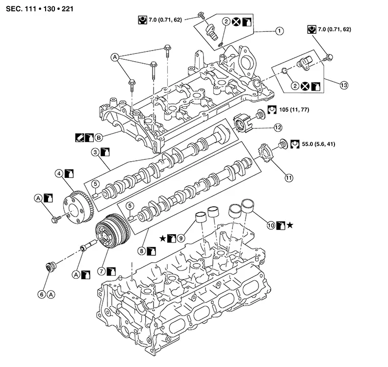
Exploded View
Exploded View
|
1. |
Exhaust camshaft position sensor (PHASE) |
2. |
O-ring |
3. |
Camshaft (EXH) |
|
4. |
Camshaft sprocket (EXH) |
5. |
Dowel |
6. |
Electric valve timing control actuator target |
|
7. |
Camshaft sprocket (INT) |
8. |
Camshaft (INT) |
9. |
Valve lifter (EXH) |
|
10. |
Valve lifter (INT) |
11. |
Signal plate (INT) |
12. |
Signal plate (EXH) |
|
13. |
Intake camshaft position sensor (PHASE) |
A. |
Refer to Removal and Installation. |
B. |
Camshaft bracket |
CAUTION:
Camshaft bracket cannot be replaced as a single part because it is machined together with the cylinder head.
 :
Identify the installation position when removing and store them
without mixing them up.
:
Identify the installation position when removing and store them
without mixing them up.
Removal and Installation
Removal and Installation
CAUTION:
The rotating direction in the text indicates all directions seen from the engine front.
REMOVAL
Remove the front cover and timing
chain. Refer to Removal and Installation.
Note: 
Removal of oil pump drive related part is not necessary.
Disconnect the harness connectors from the intake camshaft position sensor (PHASE) and exhaust camshaft position sensor (PHASE).
Remove intake camshaft position sensor (PHASE) and exhaust camshaft position sensor (PHASE) from camshaft bracket.
CAUTION:
-
Handle camshaft position sensor and exhaust valve timing control position sensor carefully and avoid impacts.
-
Do not disassemble camshaft position sensor and exhaust valve timing control position sensor.
-
Do not place sensor where it is exposed to magnetism.
-
Do not reuse O-ring.
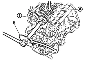
Remove the high pressure fuel tube. Refer to Exploded View.
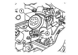
Disconnect the harness connector from the high pressure fuel pump.
Remove high pressure fuel pump (1)
and lifter.
CAUTION:
-
To prevent damage to high pressure fuel pump and camshaft bracket, loosen bolts (A) by alternating sides one turn at a time until the reaction force applied on the high pressure fuel pump disappears.
-
Do not reuse O-ring.
Remove O-ring from the high pressure fuel pump.
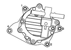
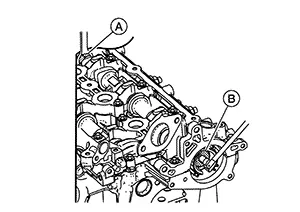
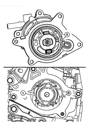
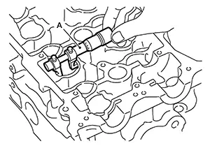
Loosen vacuum pump bolts in reverse
of the sequence shown.
Insert a suitable tool at location
(A) and separate the vacuum pump (1) from the cylinder head.
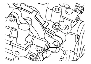
CAUTION:
-
Do not damage the mating surface.
-
The liquid gasket used at the factory is very strong. Pry only in the area shown.
-
Do not disassemble vacuum pump.
Remove bolt and reposition the water pipe. Refer to Exploded View.
If necessary, secure the hexagonal
part (A) of the camshaft (EXH) and remove the bolt (B) for the signal
plate (EXH).
Remove the electric valve timing control actuator target from the camshaft sprocket (INT).
CAUTION:
Do not reuse electric valve timing control actuator target.
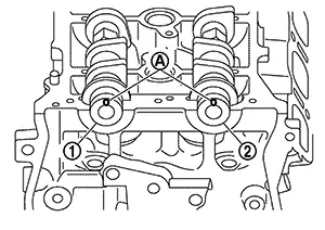
Secure the hexagonal part (A) of
the camshaft and remove the bolts and camshaft sprockets [INT (1)
and EXH (2)].
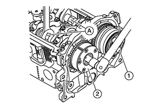
CAUTION:
-
Do not rotate crankshaft or camshaft while timing chain is removed. It causes interference between valve and piston.
-
Do not loosen the bolts with securing anything other than the camshaft hexagonal part or with tensioning the timing chain.
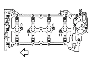
Remove camshaft bracket using the
following procedure:
Loosen camshaft bracket bolts
in reverse of the sequence shown.
|
|
: Engine front |
 ) shown in the figure, and then remove
the camshaft bracket.
) shown in the figure, and then remove
the camshaft bracket.
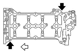
CAUTION:
-
Do not damage the mating surface.
-
The liquid gasket used at the factory is very strong. Pry only in the areas shown.
|
|
: Engine front |
Remove camshafts.
Remove valve lifters (if necessary).
-
Identify installation positions, and store them without mixing them up.
Remove signal plate from camshaft (if necessary).
INSTALLATION
CAUTION:
Do not reuse O-rings.
Install valve lifters (if necessary).
-
Install them in the original positions.
Install camshafts.
-
Clean camshaft journal to remove any foreign material.
-
Distinguish between the camshaft [INT (2)] and the camshaft [EXH (1)] by looking at the different shapes of the front and rear ends of the camshaft or using the identification colors (A/B).
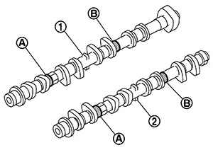
Identification color
(A)
(B)
Camshaft (EXH)
—
Blue
Camshaft (INT)
White
—
-
Install camshafts so that camshaft dowel pins (A) on the front side are positioned as shown.
 Note:
Note:
Though camshaft does not stop at the positions as shown, for the placement of cam nose, it is generally accepted camshaft is placed for the same direction of the figure.
(1)
: Camshaft (EXH)
(2)
: Camshaft (INT)
Install camshaft bracket using the
following procedure: Remove foreign material completely
from camshaft bracket backside and from cylinder head installation
face. Apply a continuous bead of liquid
gasket (C) with a suitable tool to the camshaft bracket as shown.
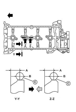
|
(A) |
: 4.0 - 5.6 mm (0.157 - 0.220 in) |
|
(B) |
: 3.4 - 4.4 mm (0.134 - 0.173 in) |
|
|
: Engine front |
|
|
: Plug hole inner wall |
|
|
: Engine outside |

Use Genuine Silicone RTV Sealant or equivalent. Refer to Recommended Chemical Products and Sealants.
CAUTION:
-
The components must be installed within 5 minutes of the liquid gasket application.
-
Do not confirm torque after the 5 minutes have elapsed.
-
Then allow 30 minutes for the liquid gasket to set before adding oil to the engine.
Note:
There are two types of mounting bolts. Refer to the following for locating bolts.
|
M6 bolts [thread length: 57.5 mm (2.264 in)] |
|
|
: 13, 14, and 15 |
|
|
M6 bolts [thread length: 35.0 mm (1.378 in)] |
|
|
: Except the above |
|
|
|
: Engine front |
-
Tighten camshaft bracket bolts to the specified torque in the sequence shown.
Camshaft bracket bolts
: 1.96 N·m (0.20 kg-m, 17 in-lb)
-
Tighten camshaft bracket bolts to the specified torque in the sequence shown.
Camshaft bracket bolts
: 5.88 N·m (0.60 kg-m, 52 in-lb)
-
Tighten camshaft bracket bolts to the specified torque in the sequence shown.
Camshaft bracket bolts
: 9.5 N·m (0.97 kg-m, 84 in-lb)
CAUTION:
After tightening camshaft bracket bolts, be sure to wipe off excessive liquid gasket from the mating surface of cylinder head.
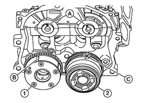
Install the camshaft sprocket to
the camshaft using the following procedure. When installing the camshaft
sprocket [INT (2)] and camshaft sprocket [EXH (3)], align the matching
mark [stamped(C)] and matching mark [groove (B) as shown.
 Tighten camshaft sprocket bolts
using the following steps.
Tighten camshaft sprocket bolts
using the following steps.
-
Secure the hexagonal part of camshaft using a suitable tool to tighten camshaft sprocket bolt.
-
Tighten camshaft sprocket bolt to the specified torque.
Camshaft sprocket bolt
: 35 N·m (3.6 kg-m, 26 ft-lb)
-
Tighten camshaft sprocket bolt by the specified angle.
CAUTION:
Check the tightening angle by using Tool (B). Do not judge by visual inspection without Tool.
Tool number (B)
: KV10112100 (BT-8653-A)
Tightening angle
: 28° - 33°
(1)
: Camshaft sprocket
(A)
: Camshaft hexagonal part
Install the timing chain and related components. Refer to Removal and Installation.
Apply clean engine oil to location
(A) shown on camshaft sprocket [INT (1)]. 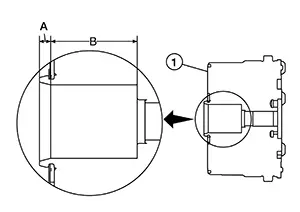 Note:
Note:
-
Do not allow any engine oil to adhere to front face of camshaft sprocket (INT).
-
Clean engine oil applied in location (B) is also acceptable.
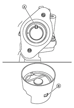
Install the electric valve timing
control actuator target into the camshaft sprocket (INT) until the
metal ring (A) clips into the groove (B) in the sprocket. 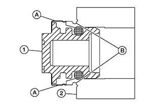
CAUTION:
Do not reuse electric valve timing control actuator target.
|
(1) |
: Electric valve timing control actuator target |
|
(2) |
: Camshaft sprocket (INT) |
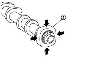
If removed, install the signal plate
(EXH) by securing the hexagonal part (A) of the camshaft (EXH). Note:
The signal plate (EXH) can only be installed in one orientation, make sure to align tabs on signal plate (EXH) with grooves in camshaft (EXH).
|
(B) |
: Signal plate bolt |
Apply a continuous bead of liquid
gasket (D) with a suitable tool to the vacuum pump (1) as shown. 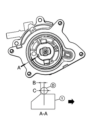
CAUTION:
-
The components must be installed within 5 minutes of the liquid gasket application.
-
Do not re-tighten bolts after the 5 minutes have elapsed.
-
Use Genuine Silicone RTV Sealant or equivalent. Refer to Recommended Chemical Products and Sealants.
|
(A) |
: View A |
|
(B) |
: 1.5 mm (0.059 in) |
|
(C) |
: 4.0 - 5.0 mm (0.157 - 0.197 in) |
|
|
: Vacuum pump outside |
Install the vacuum pump and tighten
bolts to the specified torque in the sequence shown.
|
Vacuum pump bolts |
: 10 N·m (1.0 kg-m, 89 in-lb) |
Make sure to align the tabs (A) on the back of the vacuum pump with the recesses (B) in the signal plate [INT (1)].
Install high pressure fuel pump
using the following procedure: Check the orientation of pump
cam from the mounting area of high pressure fuel pump.
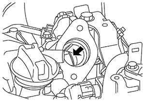 Aim pump cam at the BDC area
as shown.
Aim pump cam at the BDC area
as shown.
 Note:
Note:
For BDC area, anywhere within the area indicated
by can be accepted.
|
(1) |
: Camshaft (EXH) |
CAUTION:
-
Do not reuse O-ring.
-
Handle O-ring with bare hands. Do not wear gloves.
-
Lubricate O-ring with new engine oil.
-
Do not clean O-ring with solvent.
-
Check that O-ring and its mating part are free of foreign material.
-
Do not damage O-ring with tools and fingernails during the installation. In addition, twisting or stretching O-ring is not allowed. If O-ring is stretched during the installation to high pressure fuel pump, do not install high pressure fuel pump immediately.
 Note:
Note:
-
Lubricate the high pressure fuel pump lifter and bore of camshaft bracket.
-
When installing the high pressure fuel pump lifter, note the orientation of the protrusion (B) and cutout (A) in the camshaft bracket, they should be aligned.
|
High pressure fuel pump bolts |
: 26.5 N·m (2.7 kg-m, 20 ft-lb) |
Install the high pressure fuel tube with the following procedure.
CAUTION:
-
Do not reuse high pressure fuel tube.
-
Do not use high pressure fuel tube if its terminal tip is damaged.
-
Observe the tightening sequence and the tightening torque.
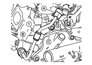 Move high pressure fuel tube
back and forth to make sure tube is seated in high pressure fuel pump
and high pressure fuel rail. Tighten flare nut (A) and flare
nut (B) until no threads are showing on high pressure fuel pump or
high pressure fuel rail.
Move high pressure fuel tube
back and forth to make sure tube is seated in high pressure fuel pump
and high pressure fuel rail. Tighten flare nut (A) and flare
nut (B) until no threads are showing on high pressure fuel pump or
high pressure fuel rail.
CAUTION:
After high pressure fuel tube is installed, make sure it does not contact adjacent parts.
Tighten high pressure fuel tube bracket bolt (C) to the specified torque.|
High pressure fuel tube bracket bolt |
: 25 N·m (2.6 kg-m, 18 ft-lb) |
|
Flare nut |
: 15 N·m (1.5 kg-m, 11 ft-lb) |
CAUTION:
Securely install the tool to flare nut before tightening.
|
Flare nut |
: 30.0 N·m (3.1 kg-m, 22 ft-lb) |
Inspect and adjust valve clearance. Refer to Inspection and Adjustment.
Installation of the remaining components is in the reverse order of removal.
Inspection
Inspection
INSPECTION AFTER REMOVAL
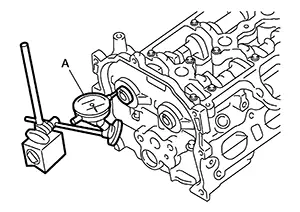
Camshaft Runout
Put V-block on a precise flat table, and support No. 2 and 5 journal of camshaft.
CAUTION:
Never support No. 1 journal (on the side of camshaft sprocket) because it has a different diameter from the other four locations.
Set
suitable tool (A) vertically to No. 3 journal.
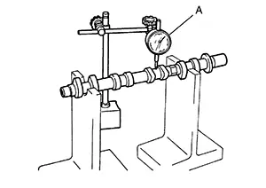
Turn camshaft to one direction with hands, and measure the camshaft runout on suitable tool. (Total indicator reading)
|
Standard and Limit |
: Refer to Camshaft. |
If it exceeds the limit, replace camshaft.
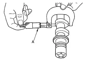
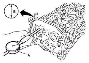
Camshaft Cam Height
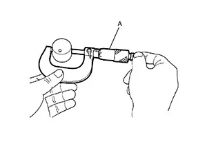
Measure the
camshaft cam height with a suitable tool (A).
|
Standard and Limit |
: Refer to Camshaft. |
If it exceeds the limit, replace camshaft.
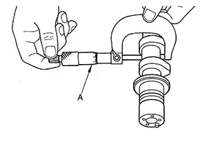
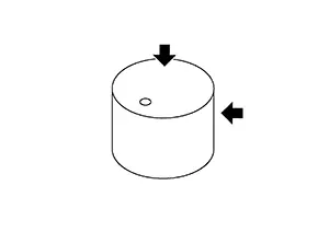
Camshaft Journal Oil Clearance
CAMSHAFT JOURNAL OUTER DIAMETER
Measure the outer diameter of camshaft journal with a suitable tool (A).
|
Standard |
: Refer to Camshaft. |
CAMSHAFT BRACKET INNER DIAMETER
-
Tighten camshaft bracket bolts with specified torque. Refer to Removal and Installation.
-
Measure the inner diameter of camshaft bracket with a suitable tool (A).
Standard
: Refer to Camshaft.
(B)
: Measuring direction of inner diameter
CAMSHAFT JOURNAL OIL CLEARANCE
-
(Oil clearance) = (Camshaft bracket inner diameter) – (Camshaft journal diameter)
Standard and Limit
: Refer to Camshaft.
-
If it exceeds the limit, replace camshaft or cylinder head, or both.
Note:
Camshaft bracket cannot be replaced as a single part, because it is machined together with cylinder head. Replace whole cylinder head assembly.
Camshaft End Play
Install camshaft in cylinder head. Refer to Removal and Installation.
Install
suitable tool in thrust direction on front end of camshaft. Read
the end play of suitable tool (A) when camshaft is moved
forward/backward (in direction to axis).
|
Standard and Limit |
: Refer to Camshaft. |
-
Measure the following parts if out of the standard.
-
Dimension (A) for groove of cylinder head No. 1 journal
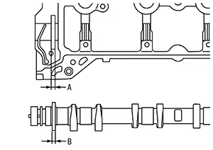
Standard
: 4.000 - 4.030 mm (0.1575 - 0.1587 in)
-
Dimension (B) for camshaft flange
Standard
: 3.877 - 3.925 mm (0.1526 - 0.1545 in)
-
-
Refer to the standards above, and then replace camshaft and/or cylinder head.
Camshaft Sprocket Runout
Put V-block on precise flat table, and support No. 2 and 5 journals of camshaft.
CAUTION:
Do not support No. 1 journal (on the side of camshaft sprocket) because it has a different diameter from the other four locations.
Measure the
camshaft sprocket runout with a suitable tool (A). (Total indicator
reading)
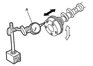
|
Limit |
: Refer to Camshaft. |
-
If it exceeds the limit, replace camshaft sprocket.
Valve Lifter
Check if surface of valve lifter has any wear or cracks.
-
If anything above is found, replace valve lifter. Refer to Camshaft.
Valve Lifter Clearance
VALVE LIFTER OUTER DIAMETER
-
Measure the outer diameter of valve lifter with a suitable tool (A).
Standard
: Refer to Camshaft.
VALVE LIFTER HOLE DIAMETER
Measure the inner diameter of valve lifter hole of cylinder head with a suitable tool (A).
|
Standard |
: Refer to Camshaft. |
VALVE LIFTER CLEARANCE
-
(Valve lifter clearance) = (Valve lifter hole diameter) – (Valve lifter outer diameter)
Standard
: Refer to Camshaft.
-
If out of the standard, referring to the each standard of valve lifter outer diameter and valve lifter hole diameter, replace either or both valve lifter and cylinder head.
INSPECTION AFTER INSTALLATION
Inspection of Camshaft Sprocket (INT), (EXH) Oil Groove
CAUTION:
-
Perform this inspection only when DTC P0014 is detected in self-diagnostic results of CONSULT and it is directed according to inspection procedure of EC section. Refer to DTC Diagnosis Procedure (P0014).
-
Check when engine is cold so as to prevent burns by the splashing engine oil.
Check engine oil level. Refer to Inspection.
Perform the following procedure so as to prevent the engine from being unintentionally started while checking. Release the fuel pressure. Refer to Work Procedure. Remove intake manifold. Refer to Removal and Installation. Disconnect the harness connectors from the ignition coils and fuel injector. Support the bottom surface of engine using a transmission jack, and then remove the engine mounting bracket (RH) and engine mounting insulator (RH). Refer to Removal and Installation.
Remove exhaust valve timing control solenoid valve. Refer to Exploded View.
-
Lift the front side of the engine with a jack base to remove intake or exhaust valve timing control solenoid valve.
Clean the mounting area of exhaust valve timing control solenoid valve, and then insert a clean waste with no oil adhesion into the oil hole of the cylinder head.
Install engine mounting insulator (RH) and engine mounting bracket (RH). (After the removal of exhaust valve timing control solenoid valve and insertion of a waste into the oil hole.)
Perform cranking to check that engine oil comes out from the oil hole (mounting hole of exhaust valve timing control solenoid valve) of cylinder head.
-
Regarding the engine oil check, judge it by the amount of oil adhered to the wasted inserted into the oil hole.
Warning:
-
Do not insert fingers into the oil hole.
-
Do not touch rotating parts (crankshaft pulley, etc.).
CAUTION:
-
Do not perform cranking without installing the engine mounting insulator (RH) and engine mounting bracket (RH).
-
Prevent splashing by using a shop cloth so as to prevent the worker from injury from engine oil and so as to prevent engine oil contamination.
-
Prevent splashing by using a shop cloth so as to prevent engine oil from being splashed to engine and Nissan Sentra vehicle. Especially, be careful not to apply engine oil to rubber parts of engine mounting insulator, etc. Wipe engine oil off immediately if it is splashed.
Perform the following inspection if engine oil does not come out from exhaust valve timing control solenoid valve oil hole of the cylinder head.
-
Clean oil groove between oil strainer and exhaust valve timing control solenoid valve. Refer to Engine Lubrication System and Engine Lubrication System Schematic.
Remove components between exhaust valve timing control solenoid valve and camshaft sprocket (EXH), and then check each oil groove for clogging.
-
Clean oil groove if necessary. Refer to Engine Lubrication System and Engine Lubrication System Schematic.
After inspection, installation is in the reverse order removal.
INSPECTION AFTER INSTALLATION
Inspection for Leakage
The following are procedures for checking fluids leakage, lubricates leakage, and exhaust gases leakage.
-
Before starting engine, check oil/fluid levels including engine coolant and engine oil. If less than required quantity, fill to the specified level. Refer to Fluids and Lubricants.
-
Use procedure below to check for fuel leakage.
-
Place ignition switch in the “ON” position (with engine stopped). With fuel pressure applied to fuel piping, check for fuel leakage at connection points.
-
Start engine. With engine speed increased, check again for fuel leakage at connection points.
-
-
Run engine to check for unusual noise and vibration.
Note:
If hydraulic pressure inside timing chain tensioner drops after removal/installation, slack in guide may generate a pounding noise during and just after the engine start. However, this does not indicate an unusualness. Noise will stop after hydraulic pressure rises.
-
Warm up engine thoroughly to check there is no leakage of fuel, or any oil/fluids including engine oil and engine coolant.
-
Bleed air from lines and hoses of applicable lines, such as in cooling system.
-
After cooling down engine, again check oil/fluid levels including engine oil and engine coolant. Refill to the specified level, if necessary.
Summary of the inspection items: Items
Before starting engine
Engine running
After engine stopped
Engine coolant
Level
Leakage
Level
Engine oil
Level
Leakage
Level
Transmission / transaxle fluid
AT & CVT Models
Leakage
Level / Leakage
Leakage
MT Models
Level / Leakage
Leakage
Level / Leakage
Other oils and fluids*
Level
Leakage
Level
Fuel
Leakage
Leakage
Leakage
Exhaust gases
—
Leakage
—
*: Power steering fluid, brake fluid, etc.
Other materials:
P061b Ecm
Dtc Description
DTC Description
DTC DETECTION LOGIC
DTC
CONSULT screen terms
(Trouble diagnosis
content)
DTC detection
condition
...
B203d-14 Inside Antenna
Dtc Description
DTC Description
DTC DETECTION LOGIC
DTC No.
CONSULT screen items
(Trouble diagnosis content)
DTC detecting condition
...
B0012-55 Active Vent
Dtc Description
DTC Description
DTC DETECTION LOGIC
DTC No.
CONSULT screen items
(Trouble diagnosis
content)
DTC Detection Condition
...