Nissan Sentra B18 (2020-2025) Service Manual: Timing Chain
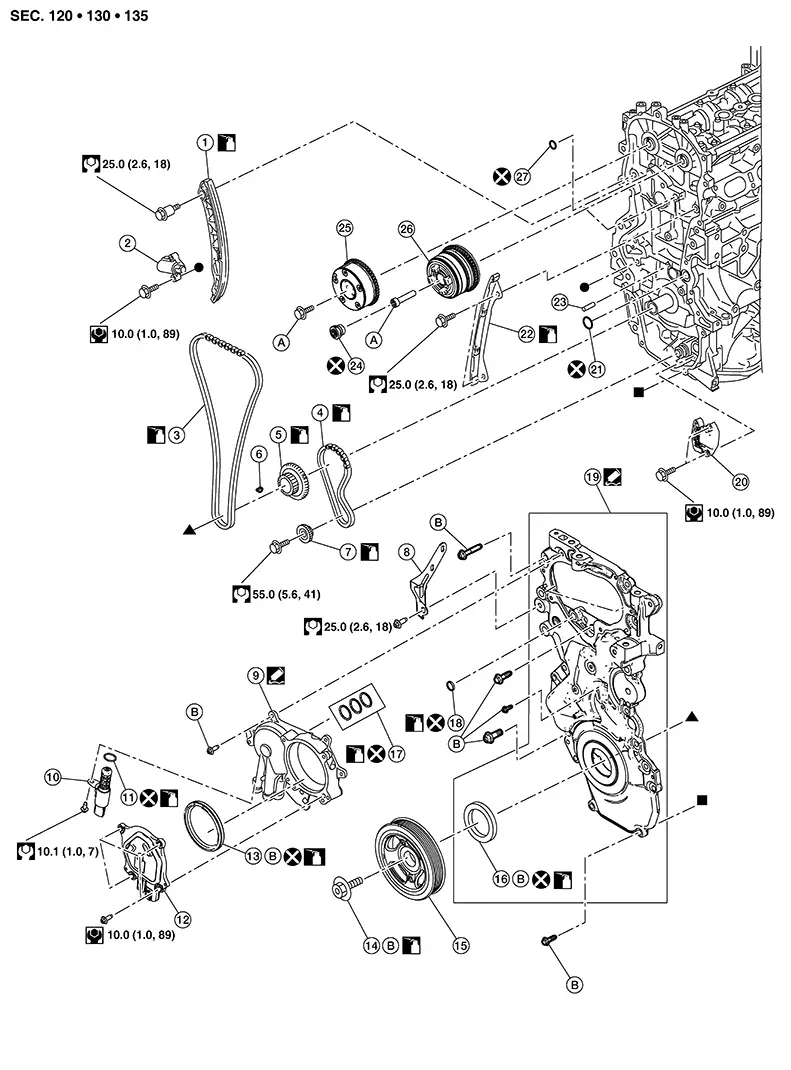
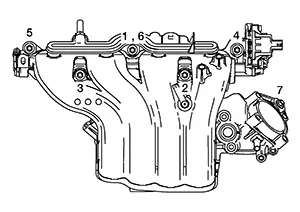
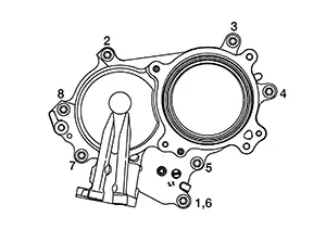
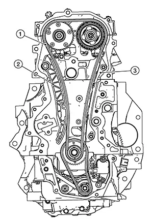
Exploded View
Exploded View
|
1. |
Slack guide |
2. |
Timing chain tensioner |
3. |
Timing chain |
|
4. |
Balancer unit timing chain |
5. |
Crankshaft sprocket |
6. |
Crankshaft key |
|
7. |
Balancer unit sprocket |
8. |
Air fuel ratio (A/F) sensor |
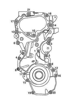
9. |
|
|
10. |
Exhaust valve timing control solenoid valve |
11. |
O-ring |
12. |
Electric intake valve timing control actuator |
|
13. |
Camshaft sprocket (INT) oil seal |
14. |
Crankshaft pulley bolt |
15. |
Crankshaft pulley |
|
16. |
Front oil seal |
17. |
O-ring |
18. |
Filter |
|
19. |
Front cover |
20. |
Balancer unit timing chain tensioner |
21. |
O-ring |
|
22. |
Timing chain tension guide |
23. |
Timing chain oil jet |
24. |
Electric intake valve timing control actuator target |
|
25. |
Camshaft sprocket (EXH) |
26. |
Camshaft sprocket (INT) |
27. |
O-ring |
|
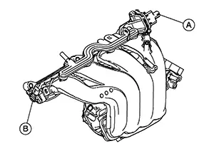
A. |
Refer to Removal and Installation. |
B. |
Refer to Removal and Installation. |
Removal and Installation
Removal and Installation
REMOVAL
CAUTION:
The rotating direction in the text indicates all directions seen from the engine front.
Mount the engine assembly to stand. Refer to Setting.
Drain engine oil. Refer to Draining.
CAUTION:
Perform this step when engine is cold.
Remove
harness retainer (A) from vacuum tube (1).
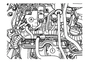
Remove bolts securing the vacuum tube. Refer to Exploded View.
Remove vacuum tube B from vacuum pump. Refer to Exploded View.
Remove the vacuum tube, vacuum hose A and vacuum hose B. Refer to Exploded View.
Remove bolts securing the vacuum delay valve bracket and remove the vacuum delay valve, vacuum delay valve bracket and EVAP hose. Refer to Exploded View.
Disconnect the harness connectors from the ignition coils.
Remove the ignition coils.
CAUTION:
-
Do not drop or shock ignition coil.
-
Do not disassemble ignition coil.
Remove engine harness retainers from rocker cover.
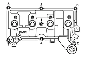
Loosen
rocker cover bolts in reverse of the sequence shown and remove
rocker cover.
Remove rocker cover gasket from rocker cover.
CAUTION:
Do not reuse rocker cover gasket.
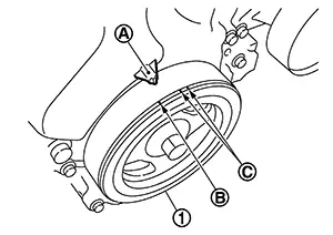
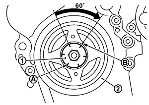
Set No. 1
cylinder at TDC on its compression stroke using the following
procedure:
Rotate crankshaft pulley (1)
clockwise and align TDC mark [no paint (B)] to timing indicator (A)
on front cover.
|
(C) |
: White paint (Not use for service) |
 ) as shown.
-
If not, rotate crankshaft pulley one revolution (360 degrees) and align as shown.
|
(1) |
: Camshaft (INT) |
|
(2) |
: Camshaft (EXH) |
|
|
: Engine front |
Disconnect the harness connector from the electric throttle control actuator.
Remove the water hose from the electric throttle control actuator. Refer to Exploded View.
Remove the water hose from the electric throttle control actuator. Refer to Exploded View.
Remove
harness retainer (A) from intake manifold.
|
(1) |
: EGR outlet tube |
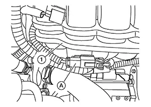
Disconnect
the harness connector (B) from the EVAP canister purge volume
control solenoid valve (1).
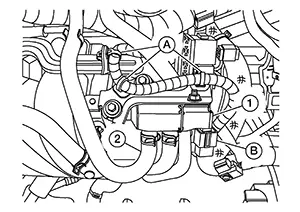
CAUTION:
Handle carefully to avoid any shock to EVAP canister purge volume control solenoid valve.
Remove the harness retainers (A) from the intake manifold and EVAP canister purge volume control solenoid valve bracket.
Remove the EVAP hose (2) from the EVAP canister purge volume control solenoid valve.
Remove the PCV hose from the intake manifold. Refer to Exploded View.
Remove the EGR volume control valve. Refer to Removal and Installation.
Remove vacuum hose A from intake manifold. Refer to Exploded View.
Disconnect the harness connector from the manifold absolute pressure (MAP) sensor.
Remove the oil level gauge.
Remove
harness retainer (A) from intake manifold.
|
(1) |
: Generator |
Remove
harness connector (A) from intake manifold (1).
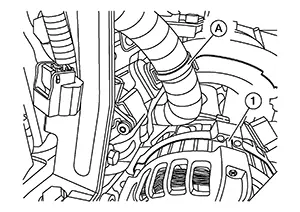
Remove
engine harness (A) from vacuum tube (1) and reposition engine
harness.
Remove
intake manifold with the following procedure:
Disconnect the harness connector
from the intake manifold runner control valve motor (A) and intake
manifold runner control valve position sensor (B).
CAUTION:
-
Handle carefully to avoid any shock to intake manifold runner control valve or intake manifold runner control valve position sensor.
-
Do not remove intake manifold runner control valve motor or intake manifold runner control valve position sensor.
CAUTION:
-
Cover engine openings to avoid entry of foreign materials.
-
Do not reuse intake manifold gasket.

Disregard No. 6 when loosening.
Remove
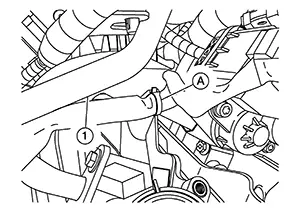
crankshaft pulley using the following procedure:
Secure crankshaft pulley (1) with a
suitable tool (A) and loosen crankshaft pulley bolt.
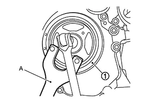
CAUTION:
Do not remove the crankshaft pulley bolt as it is used as a supporting point for a suitable puller.
Attach a suitable puller (A) in the threaded hole on crankshaft pulley (1) and remove crankshaft pulley.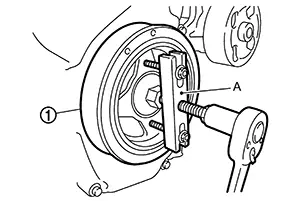
Remove oil
pan (lower) using the following procedure:
Note:
If crankshaft sprocket, balancer unit sprocket and the balancer unit timing chain are not being removed, this step is unnecessary.
Loosen oil pan (lower) bolts in reverse of the sequence shown.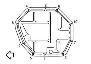
|
|
: Engine front |
CAUTION:
-
Be careful not to damage the mating surface.
-
Since factory default liquid gasket has better adhesion than conventional one, do not pick the area forcibly with a screw driver.
|
Tool number |
: KV10111100 (NI-37228) |
Remove the bolt securing air fuel ratio (A/F) sensor 1 harness bracket.
Disconnect
the harness connectors (A) from the exhaust valve timing control
solenoid valve and electric intake valve timing control
actuator.
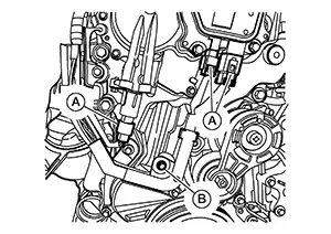
Remove bolt (B) and reposition the engine harness.
Remove exhaust valve timing control solenoid valve (if necessary).
CAUTION:
Do not reuse O-ring.
Remove bolts and remove the electric intake valve timing control actuator.
Loosen the
valve timing control cover bolts in reverse of the sequence shown
and remove the valve timing control cover.
 Note:
Note:
Disregard No. 6 when loosening.
Remove the camshaft sprocket (INT) oil seal from the valve timing control cover (if necessary).
CAUTION:
Do not reuse camshaft sprocket (INT) oil seal if removed.
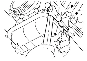
Remove
front cover using the following procedure:
Loosen front cover bolts in reverse
of the sequence shown.
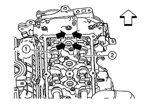
 Cut
liquid gasket by prying the position ()
shown and then remove the front cover.
Cut
liquid gasket by prying the position ()
shown and then remove the front cover.
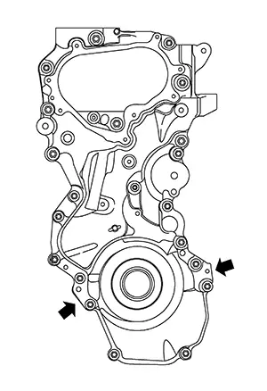
CAUTION:
-
Do not damage the mating surface.
-
The liquid gasket used at the factory is very strong. Pry only in the areas shown.
Remove front oil seal from front cover.
CAUTION:
-
Be careful not to damage front cover.
-
Do not reuse front oil seal.
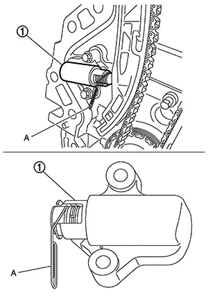
Remove
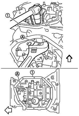
timing chain tensioner using the following procedure:
Push
in timing chain tensioner plunger.
Insert a suitable tool (A) into the
body hole, and then fix it with the plunger pushed in.
|
(1) |
: Timing chain tensioner |
CAUTION:
Do not remove suitable tool (A) from timing chain tensioner when removed from Nissan Sentra vehicle. If timing chain tensioner plugger becomes fully extended, replace timing chain tensioner.
Remove
slack guide (2), timing chain tension guide (3) and timing chain
(1).
CAUTION:
Do not rotate the crankshaft and camshafts individually while timing chain is removed. It causes interference between valve and piston.
Remove
crankshaft sprocket and balancer unit drive component using the
following procedure:
Press
the balancer unit timing chain slack guide (A) toward balancer unit
timing chain tensioner (1).
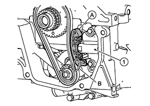 Insert a suitable tool (B) into hole
in tensioner body to secure the balancer unit timing chain slack
guide.
Remove balancer unit timing chain
tensioner. Hold
the WAF part of balancer shaft [WAF: 19 mm (0.75 in)] (A), and then
loosen the balancer unit sprocket bolt.
Insert a suitable tool (B) into hole
in tensioner body to secure the balancer unit timing chain slack
guide.
Remove balancer unit timing chain
tensioner. Hold
the WAF part of balancer shaft [WAF: 19 mm (0.75 in)] (A), and then
loosen the balancer unit sprocket bolt.
CAUTION:
-
Secure the balancer unit shaft with the WAF part.
-
Do not loosen the balancer unit sprocket bolt by tightening the balancer unit timing chain.
|
(1) |
: Oil pan (upper) |
|
|
: Engine front |
INSTALLATION
Check that crankshaft key points straight up.
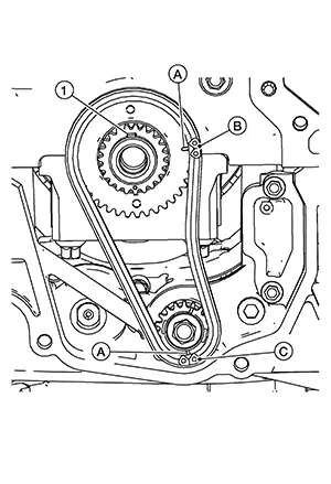
Install
crankshaft sprocket (2), balancer unit sprocket (3) and balancer
unit timing chain (1).
|
(A) |
: Matching mark (stamping) |
|
(B) |
: Matching mark (white link) |
|
(C) |
: Matching mark (dark blue link) |
-
Install it by aligning matching marks on each sprocket and balancer unit timing chain.
-
If these matching marks are not aligned, rotate the balancer shaft slightly to correct the position.
CAUTION:
Check matching mark position of each sprocket after installing the balancer unit timing chain.
Hold the
WAF part of balancer unit shaft [WAF: 19 mm (0.75 in)] (A) and then
tighten the balancer shaft sprocket bolt.
CAUTION:
-
Secure the balancer unit shaft with the WAF part.
-
Do not loosen the balancer shaft sprocket bolt by tightening the balancer unit timing chain.
|
(1) |
: Oil pan (upper) |
|
|
: Engine front |
Install
balancer unit timing chain tensioner (1).
-
Fix the balancer unit timing chain slack guide (A) at the most compressed position using a suitable tool (B) and then install it.
-
Securely remove the suitable tool after installing the balancer unit timing chain tensioner.
-
Check matching mark position of balancer unit timing chain and each sprocket again.
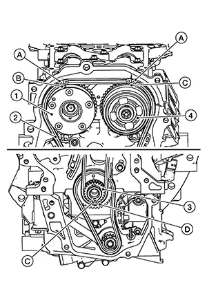
Align the
matching marks of each sprocket with the matching marks of timing
chain.
|
(1) |
: Camshaft sprocket (EXH) |
|
(2) |
: Timing chain |
|
(3) |
Crankshaft sprocket |
|
(4) |
: Camshaft sprocket (INT) |
|
(A) |
: Matching mark (dark blue link) |
|
(B) |
: Matching mark (groove) |
|
(C) |
: Matching mark (stamping) |
|
(D) |
: Matching mark (white link) |
-
If these matching marks are not aligned, rotate the camshaft slightly by holding the hexagonal portion to correct the position.
CAUTION:
Check matching mark position of each sprocket and timing chain again after installing the timing chain.
Install the
timing chain tension guide (3) and the slack guide (2).
|
(1) |
: Timing chain |
Install the
timing chain tensioner (1).
-
Securely pull out the suitable tool after installing the timing chain tensioner.
CAUTION:
Do not remove suitable tool (A) from timing chain tensioner when removed from Nissan Sentra vehicle. If timing chain tensioner plugger becomes fully extended, replace timing chain tensioner.
Check matching mark position of timing chain and each sprocket again.
Install front oil seal. Refer to Removal and Installation.
Install front cover with the following procedure: Install new O-rings to cylinder block.
CAUTION:
-
Do not reuse O-rings.
-
Make sure O-rings are not misaligned.
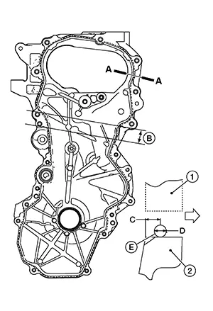 Note:
Note:
When applying liquid gasket in location (B), apply a bead of liquid sealant with a diameter of 6.0 - 7.0 mm (0.236 - 0.279 in).
|
(1) |
: Cylinder block, oil pan (upper), cylinder head |
|
(C) |
: 4.0 - 5.6 mm (0.157 - 0.220 in) |
|
(D) |
: 3.4 - 4.4 mm (0.134 - 0.173 in) |
|
|
: Engine outside |
Use Genuine Silicone RTV Sealant or equivalent. Refer to Recommended Chemical Products and Sealants.
CAUTION:
-
The components must be installed within 5 minutes of the liquid gasket application.
-
Do not confirm torque after the 5 minutes have elapsed.
-
Then allow 30 minutes for the liquid gasket to set before adding oil to the engine.
CAUTION:
-
Check O-rings on cylinder block are correctly installed.
-
Be careful not to damage front oil seal by interference with front end of crankshaft.
-
Refer to the following for the installation position of bolts.
No. 1
: 6.6 N·m (0.67 kg-m, 58 in-lb)
No. 6, 7, 13, 21
: 55.0 N·m (5.6 kg-m, 41 ft-lb)
No. 10
: 55.0 N·m (5.6 kg-m, 41 ft-lb)
Except the above
: 25.5 N·m (2.6 kg-m, 19 ft-lb)
CAUTION:
-
The components must be installed within 5 minutes of the liquid gasket application.
-
Be sure to wipe off any excessive liquid gasket.
-
Then allow 30 minutes for the liquid gasket to set before adding oil to the engine.
Install valve timing control cover using o the following instructions: Install O-rings onto valve timing control cover.
CAUTION:
Do not reuse O-rings.
If removed, install the camshaft sprocket (INT) oil seal with Tool.CAUTION:
Do not reuse camshaft sprocket (INT) oil seal.
-
Insert the camshaft sprocket (INT) oil seal (2) into the valve timing control cover (1) to the specified depth (A) or until Tool contacts valve timing control cover.
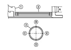
Tool
: — (NI-52553)
(A)
: 13.4 - 15.0 mm (0.528 - 0.591 in)
-
Measure the depth of the camshaft sprocket (INT) oil seal (2) at positions (B) and (D). The difference should not exceed 0.8 mm (0.031 in). Repeat measurements at positions (C) and (E).
|
(1) |
: Front cover |
|
(2) |
: valve timing control cover |
|
(A) |
: View A |
|
(B) |
: 4.0 - 5.6 mm (0.157 - 0.220 in) |
|
(D) |
: φ3.4 - 4.4 mm (0.134 - 0.173 in) |
Use Genuine Silicone RTV Sealant or equivalent. Refer to Recommended Chemical Products and Sealants.
CAUTION:
-
The components must be installed within 5 minutes of the liquid gasket application.
-
Do not confirm torque after the 5 minutes have elapsed.
-
Then allow 30 minutes for the liquid gasket to set before adding oil to the engine.
Overlap the start and end of liquid gasket application positions at least 5 mm (0.20 in).
Install filter to groove in front cover.CAUTION:
Do not reuse filter.
Align valve timing control cover with dowel pins in front cover and install valve timing control cover. Tighten the valve timing control cover bolts to the specified torque in the sequence shown.
CAUTION:
Be sure to wipe off any excess liquid gasket.
|
Valve timing control cover bolts |
: 10.0 N·m (1.0 kg-m, 89 in-lb) |
Install crankshaft pulley using the following procedure: When inserting crankshaft pulley with a suitable tool, tap on its center portion (not circumference).
CAUTION:
Do not damage front oil seal lip portion.
Secure crankshaft pulley (1) with a suitable tool (A). Apply
new engine oil to thread and seat surfaces of crankshaft pulley
bolt.
Tighten crankshaft pulley bolt to
the specified torque. |
Crankshaft pulley bolt |
: 29.4 N·m (3.0 kg-m, 22 ft-lb) |
 Tighten crankshaft pulley bolt to
the specified angle using Tool.
Tighten crankshaft pulley bolt to
the specified angle using Tool.
-
Check the tightening angle with movement of one angle mark.
CAUTION:
Check and confirm the tightening angle using Tool. Avoid judgement by visual inspection without Tool.
Tool number
: KV10112100 (BT-8653-A)
Tightening angle
: 60° - 66°
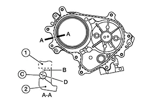
Install oil
pan (lower) using the following procedure:
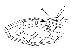
Use a
suitable tool (A) to remove old liquid gasket from mating
surfaces.
-
Also remove old liquid gasket from mating surface of oil pan (upper).
-
Remove old liquid gasket from the bolt holes and threads.
CAUTION:
Do not scratch or damage the mating surface when cleaning off old liquid gasket.
Apply a continuous bead of liquid gasket (C) with a suitable tool as shown.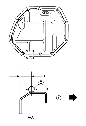
|
(1) |
: Oil pan (lower) |
|
(B) |
: 7.5 - 8.5 mm (0.295 - 0.374 in) |
|
(D) |
: 4.0 - 5.0 mm (0.157 - 0.197 in) |
|
|
: Engine outside |
Use Genuine Silicone RTV Sealant or equivalent. Refer to Recommended Chemical Products and Sealants.
CAUTION:
-
The components must be installed within 5 minutes of the liquid gasket application.
-
Do not confirm torque after 5 minutes have elapsed.
-
Then allow 30 minutes for the liquid gasket to set before adding oil to the engine.
|
Oil pan (lower) bolts |
: 10.1 N·m (1.0 kg-m, 7 ft-lb) |
Install drain plug. Refer to Exploded View.
CAUTION:
Do not reuse drain plug washer.
Install the intake manifold gasket into the groove of intake manifold.
CAUTION:
Do not reuse intake manifold gasket.
Install the
intake manifold using the following procedure:
Hand
tighten bolts 4 and 5 as shown.
Tighten the intake manifold bolts to
the specified torque in the sequence shown.
|
Intake manifold bolts |
: 25.0 N·m (2.6 kg-m, 18 ft-lb) |
Install the rocker cover gasket to rocker cover.
CAUTION:
Do not reuse rocker cover gasket.
Note:
Make sure rocker cover gasket is installed into groove in rocker cover.
Install the
rocker cover and tighten the bolts to the specified torque in the
sequence shown.
|
Step 1 |
: 1.96 N·m (0.20 kg-m, 17 in-lb) |
|
Step 2 |
: 8.33 N·m (0.85 kg-m, 74 in-lb) |
Installation of the remaining components is in the reverse order of removal.
-
Refill the engine oil. Refer to Refilling.
Inspection
Inspection
INSPECTION AFTER REMOVAL
Timing Chain
Check for cracks (A) and any excessive wear (B) at link plates and roller links of timing chain.
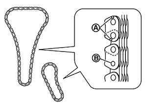
Replace timing chain if necessary.
INSPECTION AFTER INSTALLATION
Inspection for Leakage
The following are procedures for checking fluids leakage, lubricates leakage, and exhaust gases leakage.
-
Before starting engine, check oil/fluid levels including engine coolant and engine oil. If less than required quantity, fill to the specified level. Refer to Fluids and Lubricants.
-
Use procedure below to check for fuel leakage.
-
Place ignition switch in the “ON” position (with engine stopped). With fuel pressure applied to fuel piping, check for fuel leakage at connection points.
-
Start engine. With engine speed increased, check again for fuel leakage at connection points.
-
-
Run engine to check for unusual noise and vibration.
Note:
If hydraulic pressure inside timing chain tensioner drops after removal/installation, slack in guide may generate a pounding noise during and just after the engine start. However, this does not indicate an unusualness. Noise will stop after hydraulic pressure rises.
-
Warm up engine thoroughly to check there is no leakage of fuel, or any oil/fluids including engine oil and engine coolant.
-
Bleed air from lines and hoses of applicable lines, such as in cooling system.
-
After cooling down engine, again check oil/fluid levels including engine oil and engine coolant. Refill to the specified level, if necessary.
Summary of the inspection items: Items
Before starting engine
Engine running
After engine stopped
Engine coolant
Level
Leakage
Level
Engine oil
Level
Leakage
Level
Transmission / transaxle fluid
AT & CVT Models
Leakage
Level / Leakage
Leakage
MT Models
Level / Leakage
Leakage
Level / Leakage
Other oils and fluids*
Level
Leakage
Level
Fuel
Leakage
Leakage
Leakage
Exhaust gases
—
Leakage
—
*: Power steering fluid, brake fluid, etc.
Other materials:
C1714-7b Low Tire Pressure Rr
Dtc Description
DTC Description
Note:
The Signal Tech II Tool [– (NI-50190)] can be used
to perform the following functions: Refer to the Signal Tech II User
Guide for additional information.
Activate and display TPMS sensor IDs
Display tire pressure rep ...
P1217 Engine Over Temperature
Dtc Description
DTC Description
ECM controls cooling fan to the maximum speed when receives the
signal abnormality of each sensor, CAN and IPDM E/R, and severed wire short
circuit abnormality.
If the cooling fan or another component in the cooling system
malfunctions, engine coola ...
Engine cooling system
The engine cooling system of the Nissan Sentra is factory-filled with a pre-diluted
mixture consisting of 50% Genuine NISSAN Long Life Antifreeze/Coolant (blue) and
50% water. This formulation is designed to provide reliable, year-round antifreeze
protection and effective engine cooling perfor ...