Nissan Sentra B18 (2020-2025) Service Manual: Rear Door Lock
Exploded View
Exploded View
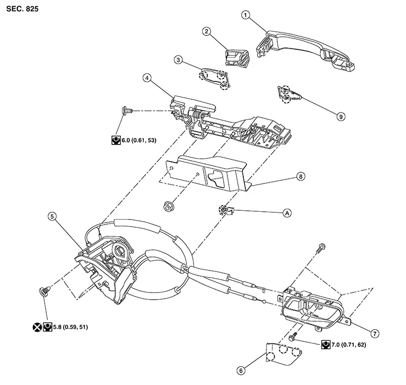
|
1. |
Outside handle |
2. |
Outside handle escutcheon |
3. |
Rear gasket |
|
4. |
Outside handle bracket A |
5. |
Rear door lock |
6. |
Inside handle escutcheon |
|
7. |
Inside handle |
8. |
Outside handle bracket B |
9. |
Front gasket |
|
A. |
Cable clip |
|
Pawl |

Door Lock
Removal and Installation
Removal and Installation
REMOVAL
Remove outside handle. Refer to Removal and Installation.
Remove bolts and door lock.
INSTALLATION
Installation is in the reverse order of removal.
CAUTION:
-
Do not reuse rear door lock bolts.
-
After installation, check door lock cables are properly engaged to inside handle and outside handle.
-
After installation, check door open/close and lock/unlock operation.
Inside Handle
Removal and Installation
Removal and Installation
REMOVAL
Remove rear door finisher. Refer to Removal and Installation.
Remove screws and door inside handle.
INSTALLATION
Installation is in the reverse order of removal.
CAUTION:
-
After installation, check door lock cables are properly engaged to inside handle.
-
After installation, check door open/close and lock/unlock operation.
Outside Handle
Removal and Installation
Removal and Installation
REMOVAL
Fully close rear door glass.
Remove rear door finisher. Refer to Removal and Installation.
Disconnect the harness connector from the rear door lock and release harness clip.
Remove rear door vapor barrier.
Remove rear door rear run screw and bolts and remove rear run rear bracket. Refer to Exploded View.
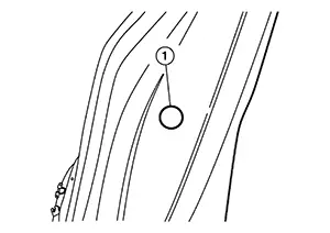
Remove door
side grommet (1) and loosen bolt from grommet hole.
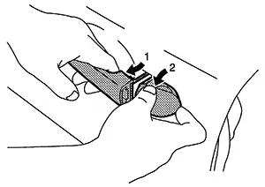
While
pulling outside handle, remove outside handle escutcheon as
shown.
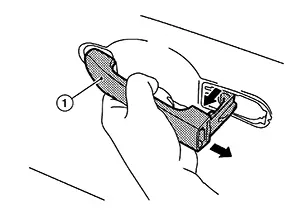
While
pulling outside handle (1), slide toward rear of Nissan Sentra vehicle to remove
outside handle as shown.
Remove
front gasket (1) and rear gasket (2) as shown.
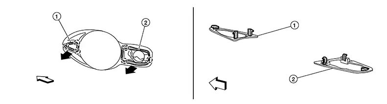
|
|
:Pawl |
|
|
:Front |

Slide
outside handle bracket toward rear of Nissan Sentra vehicle to remove as
shown.
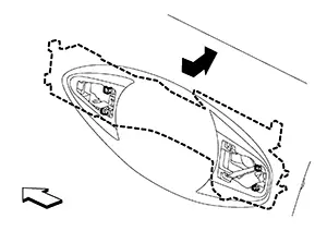
|
|
:Front |
Disconnect
outside handle cable (1) from outside handle bracket (2) in
sequence shown.
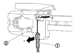
INSTALLATION
Installation in the reverse order of removal.
CAUTION:
-
After installation, check door lock cable is properly engaged to outside handle bracket.
-
After installation, check door open/close and lock/unlock operation.
Other materials:
Noise, Vibration and Harshness (nvh) Troubleshooting. Nvh Troubleshooting Chart
Nvh Troubleshooting Chart
NVH Troubleshooting Chart
Use the chart below to find the cause of the
symptom. If necessary, repair or replace these parts.
...
Accelerator Control System. Removal and Installation. Accelerator Control System
Accelerator Control System
Exploded View
Exploded View
1.
Accelerator pedal
assembly
2.
Brake pedal bracket
...
P1526 Vehicle Speed Sensor
Dtc Description
DTC Description
DTC DETECTION LOGIC
DTC
CONSULT screen terms
(Trouble diagnosis
content)
DTC detection
condition
...