Nissan Sentra B18 (2020-2025) Service Manual: P2101 Electric Throttle Control Function
Dtc Description
DTC Description
DTC DETECTION LOGIC
|
DTC |
CONSULT screen terms (Trouble diagnosis content) |
DTC detection condition |
|
|
P2101 |
ETC FNCTN/CIRC-B1 (Throttle actuator ŌĆ£AŌĆØ control motor circuit range/performance) |
Diagnosis condition |
Engine running at idle |
|
Signal (terminal) |
ŌĆö |
||
|
Threshold |
Electric throttle control function does not operate properly |
||
|
Diagnosis delay time |
ŌĆö |
||
POSSIBLE CAUSE
-
Harness or connectors
-
Throttle control motor circuit is open or shorted.
-
Throttle control motor relay circuit is open or shorted.
-
-
Electric throttle control actuator
FAIL-SAFE
Engine Control System
|
Engine operating condition in fail-safe mode |
||
|---|---|---|
|
Fail safe mode |
Nissan Sentra Vehicle behavior |
|
|
Device fix mode |
|
|
|
Others |
ECM stops the electric throttle control actuator control, throttle valve is maintained at a fixed opening (approx. 5 degrees) by the return spring. |
|
Idle Start/Stop System
When a DTC is detected, the start/stop indicator lamp blinks slowly and the idle start/stop system operation is prohibited.
When ECM detects error while operating the idle start/stop system, ECM restarts the engine.
Confirmation Procedure
Confirmation Procedure
-
CHECK DTC PRIORITY
If DTC P2101 is displayed with DTC P2100 or P2119, first perform the trouble diagnosis for DTC P2100 or P2119.
Is applicable DTC detected?
YES >>Perform diagnosis of applicable.
-
DTC P2100: Refer to DTC Description.
-
DTC P2119: Refer to DTC Description.
GO TO 2.
-
-
PRECONDITIONING
If DTC Confirmation Procedure has been previously conducted, always perform the following procedure before conducting the next test.
-
Turn ignition switch OFF and wait at least 10 seconds.
-
Turn ignition switch ON.
-
Turn ignition switch OFF and wait at least 10 seconds.
TESTING CONDITION:
Before performing the following procedure, confirm that battery voltage is more than 11 V at idle.
>>GO TO 3.
-
-
PERFORM DTC CONFIRMATION PROCEDURE
-
Turn ignition switch ON and wait at least 2 seconds.
-
Start engine and let it idle for 5 seconds.
-
Check DTC.
Is DTC detected?
YES >>Proceed to DTC Diagnosis Procedure.
NO-1 >>To check malfunction symptom before repair: Refer to Intermittent Incident.
NO-2 >>Confirmation after repair: INSPECTION END
-
Dtc Diagnosis Procedure
DTC Diagnosis Procedure
-
CHECK DTC PRIORITY
If DTC P2101 is displayed with DTC P2100 or P2119, first perform the trouble diagnosis for DTC P2100 or P2119.
Is applicable DTC detected?
YES >>Perform diagnosis of applicable.
-
DTC P2100: Refer to DTC Description.
-
DTC P2119: Refer to DTC Description.
GO TO 2.
-
-
CHECK THROTTLE CONTROL MOTOR RELAY INPUT SIGNAL
Check the voltage between ECM harness connector terminals as per the following conditions.
+
ŌłÆ
Condition
Voltage
(Approx.)
ECM
Connector
Terminal
Connector
Terminal
F25
97
E16
162
Ignition switch
OFF
0 V
ON
Battery voltage
Is the inspection result normal?
YES >>GO TO 5.
NO >>GO TO 3.
-
CHECK THROTTLE CONTROL MOTOR RELAY INPUT SIGNAL CIRCUIT
-
Turn ignition switch OFF.
-
Disconnect ECM harness connector.
-
Disconnect IPDM E/R harness connector.
-
Check the continuity between ECM harness connector and IPDM E/R harness connector.
ECM
IPDM E/R
Continuity
Connector
Terminal
Connector
Terminal
F25
97
F96
67
Existed
-
Also check harness for short to ground and to power.
Is the inspection result normal?
YES >>GO TO 4.
NO >>Repair or replace malfunctioning part.
-
-
CHECK THROTTLE CONTROL MOTOR RELAY POWER SUPPLY CIRCUIT
-
Check the continuity between ECM harness connector and IPDM E/R harness connector.
ECM
IPDM E/R
Continuity
Connector
Terminal
Connector
Terminal
F25
128
F96
72
Existed
-
Also check harness for short to ground and to power.
Is the inspection result normal?
YES >>Perform the trouble diagnosis for power supply circuit.
NO >>Repair or replace malfunctioning part.
-
-
CHECK THROTTLE CONTROL MOTOR OUTPUT SIGNAL CIRCUIT
-
Turn ignition switch OFF.
-
Disconnect electric throttle control actuator harness connector.
-
Disconnect ECM harness connector.
-
Check the continuity between electric throttle control actuator harness connector and ECM harness connector.
Electric throttle control actuator
ECM
Continuity
Connector
Terminal
Connector
Terminal
F7
5
F25
129
Existed
130
Not existed
6
129
Not existed
130
Existed
-
Also check harness for short to ground and to power.
Is the inspection result normal?
YES >>GO TO 6.
NO >>Repair or replace malfunctioning part.
-
-
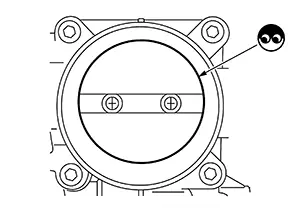
CHECK ELECTRIC THROTTLE CONTROL ACTUATOR VISUALLY
-
Remove the intake air duct. Refer to Removal and Installation.
-
Check if foreign matter is caught between the throttle valve and the housing.
Is the inspection result normal?
YES >>GO TO 7.
NO >>Remove the foreign matter and clean the electric throttle control actuator inside, then perform throttle valve closed position learning. Refer to Work Procedure.
-
-
CHECK THROTTLE CONTROL MOTOR
Check the throttle control motor. Refer to Component Inspection.
Is the inspection result normal?
YES >>INSPECTION END
NO >>Replace electric throttle control actuator. Refer to Removal and Installation.
Other materials:
Exterior. Symptom Diagnosis. Squeak and Rattle Trouble Diagnoses
Squeak and Rattle Trouble Diagnoses
Work Flow
Work Flow
CUSTOMER INTERVIEW
Interview the customer if possible, to determine
the conditions that exist when the noise occurs. Use the Diagnostic
Worksheet during the interview to document the facts and conditions
when the noise occu ...
Engine cooling system
The engine cooling system of the Nissan Sentra is factory-filled with a pre-diluted
mixture consisting of 50% Genuine NISSAN Long Life Antifreeze/Coolant (blue) and
50% water. This formulation is designed to provide reliable, year-round antifreeze
protection and effective engine cooling perfor ...
Heater and air conditioner (automatic)
AUTO (automatic) climate control button / temperature control dial (driver's
side)
Display screen
Heated seat switches (if so equipped)
SYNC button / temperature control dial (passenger's side)
A/C (air conditioner) button
Air recirculation button
A ...