Nissan Sentra Service Manual: Rear disc brake
Exploded View
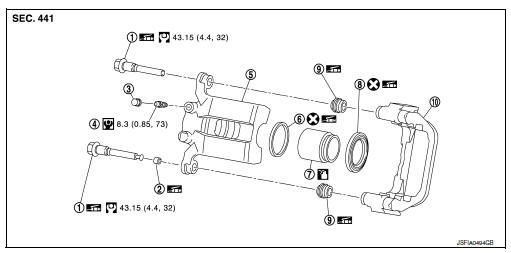
- Sliding pin bolt
- Bushing
- Cap
- Bleeder valve
- Cylinder body
- Piston seal
- Piston
- Piston boot
- Sliding pin boot
- Torque member
 Apply rubber grease
 Apply brake fluid
Disassembly and Assembly
DISASSEMBLY
- Place a wooden block as shown, and blow air from union bolt hole to remove piston and piston boot.
WARNING:
Do not get fingers caught between piston and cylinder body.
- Remove piston seal from cylinder body using suitable tool.
CAUTION:
Do not damage cylinder inner wall.
- Remove bleeder valve and cap.
ASSEMBLY
- Install bleeder valve and cap.
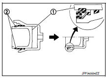
- Apply rubber grease to piston seal (1), and install to cylinder body.
CAUTION:
Do not reuse piston seal.
- Apply rubber grease to piston boot (1). Cover the piston (2) end with piston boot, and install cylinder side lip on piston boot securely into a groove on cylinder body.
CAUTION:
Do not reuse piston boot.
- Apply new brake fluid to piston (1). Push piston into cylinder body by hand and push piston boot (2) piston-side lip into the piston groove.
CAUTION:
Press the piston evenly and vary the pressing point to prevent cylinder inner wall from being rubbed.
 Rear drum brake
Exploded View
Cap
Bleeder valve
Piston
Spring
Boot
Piston cup
Wheel cylinder
Apply rubber grease
Apply PBC (Poly Butyl Cuprysil)
grease or silicone-based grease
Apply ...
 Service data and specifications (SDS)
General Specifications
Brake Pedal
Check Valve
Brake Booster
Front Disc Brake
Rear Drum Brake
Rear Disc Brake
...
Other materials:
Chassis and body maintenance
In-cabin microfilter
In-cabin microfilter : removal and installation
REMOVAL
Remove the in-cabin microfilter cover.
CAUTION:
Before removing the in-cabin microfilter cover, let the vehicle rest
for at least 30 minutes.
Release the filter cover tab (A), then pull the bottom of the in- ...
Ipdm-e branch line circuit
Diagnosis procedure
1.Check connector
Turn the ignition switch OFF.
Disconnect the battery cable from the negative terminal.
Check the terminals and connectors of the IPDM E/R for damage, bend and
loose connection (unit side
and connector side).
Is the inspection result normal?
Yes ...
C1164, C1165, C1166, C1167 CV/SV System
DTC Logic
Dtc detection logic
DTC
Display Item
Malfunction detected condition
Possible causes
C1164
CV 1
When a malfunction is detected in cut valve 1.
Harness or connector
ABS actuator and electric unit
(control unit)
Fusible link
Battery ...
