Nissan Sentra Service Manual: Rear drum brake
Exploded View
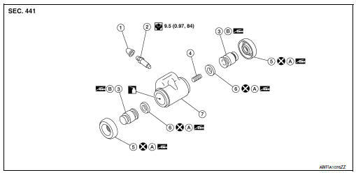
- Cap
- Bleeder valve
- Piston
- Spring
- Boot
- Piston cup
- Wheel cylinder
- Apply rubber grease
- Apply PBC (Poly Butyl Cuprysil) grease or silicone-based grease
 Apply brake fluid
Disassembly and Assembly
DISASSEMBLY
- Remove the boot from wheel cylinder. Refer to BR-51, "Exploded View".
- Remove the piston, piston cup and spring from wheel cylinder.
CAUTION:
Pull the piston out from the wheel cylinder to prevent the wheel cylinder inner wall from being damaged.
- Remove piston cup from piston.
ASSEMBLY
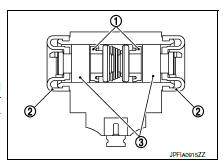
- Apply rubber grease to the piston cup (1) and boot (2).
- Install piston cup and boot to piston (3).
CAUTION:
- Do not mistake the direction.
- Do not reuse piston cup and boot.
- Apply PBC (Poly Butyl Cuprysil) grease or silicone-based grease to the piston. Apply new brake fluid to wheel cylinder inner wall. Install spring, piston cover, and piston to wheel cylinder.
CAUTION:
Do not damage the wheel cylinder inner wall.
- Install the boot to wheel cylinder. Refer to BR-51, "Exploded View".
 Front disc brake
Exploded View
Cap
Bleeder valve
Cylinder body
Piston seal
Piston
Piston boot
Upper sliding pin
Lower sliding pin
Sliding pin boot
Bushing
Torque member
Apply brake flui ...
 Rear disc brake
Exploded View
Sliding pin bolt
Bushing
Cap
Bleeder valve
Cylinder body
Piston seal
Piston
Piston boot
Sliding pin boot
Torque member
Apply rubber grease
Apply brake flui ...
Other materials:
Precaution
Precaution for supplemental restraint system (srs) "air bag" and "seat
belt pre-tensioner"
The supplemental restraint system such as đ▓đéĐÜair bagđ▓đéĐť and đ▓đéĐÜseat belt pre-tensionerđ▓đéĐť,
used along
with a front seat belt, helps to reduce the risk or severity of injur ...
Rear lh side power window does not operate
When both power window main switch and rear power window switch lh are
operated
When both power window main switch and rear power window switch lh are
operated : diagnosis procedure
1.CHECK REAR POWER WINDOW SWITCH LH
Check rear power window switch LH.
Refer to PWC-40, "REAR POWER WIN ...
How to use the APPS ÔÇô i button
For more information about the ÔÇťSiriusXM Travel
LinkÔÇŁ, and ÔÇťSiriusXM TrafficÔÇŁ features, see the
separate Navigation System OwnerÔÇÖs Manual.
For more information about the ÔÇťMy AppsÔÇŁ key,
see ÔÇťNissanConnectÔäó App Smartphone IntegrationÔÇŁ
in this section.
For more infor ...
