Nissan Sentra Service Manual: Front disc brake
Exploded View
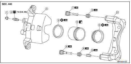
- Cap
- Bleeder valve
- Cylinder body
- Piston seal
- Piston
- Piston boot
- Upper sliding pin
- Lower sliding pin
- Sliding pin boot
- Bushing
- Torque member
 Apply brake fluid
 Apply rubber grease
Disassembly and Assembly
DISASSEMBLY
- Place a wooden block as shown, and blow air from union bolt hole to remove piston and piston boot.
WARNING:
Do not get fingers caught between piston and cylinder body.
- Remove piston seal from cylinder body u.
CAUTION:
Do not damage cylinder inner wall.
- Remove bleeder valve and cap.
ASSEMBLY
- Install bleeder valve and cap.
- Apply rubber grease to piston seal (1), and install to cylinder body.
CAUTION:
Do not reuse piston seal.
- Apply rubber grease to piston boot (1). Cover the piston (2) end with piston boot, and install cylinder side lip on piston boot securely into a groove on cylinder body.
CAUTION:
Do not reuse piston boot.
- Apply new brake fluid to piston (1). Push piston into cylinder body by hand and push piston boot (2) piston-side lip into the piston groove.
CAUTION:
Press the piston evenly and vary the pressing point to prevent cylinder inner wall from being rubbed.

 Rear drum brake
Exploded View
Cap
Bleeder valve
Piston
Spring
Boot
Piston cup
Wheel cylinder
Apply rubber grease
Apply PBC (Poly Butyl Cuprysil)
grease or silicone-based grease
Apply ...
Other materials:
Throttle valve closed position
learning
Description
Throttle Valve Closed Position Learning is a function of ECM to learn the
fully closed position of the throttle
valve by monitoring the throttle position sensor output signal. It must be
performed each time the harness connector
of the electric throttle control actuator or ECM is ...
Heater and Air Conditioner (manual) (if so equipped)
WARNING
The air conditioner cooling function operates
only when the engine is running.
Do not leave children or adults who would
normally require the assistance of others
alone in your vehicle. Pets should also not
be left alone. They could accidentally injure
them ...
C1704, C1705, C1706, C1707 Low tire pressure
DTC Logic
NOTE:
The Signal Tech II Tool (J-50190) can be used to perform the following
functions. Refer to the Signal Tech II
User Guide for additional information.
Activate and display TPMS transmitter IDs
Display tire pressure reported by the TPMS transmitter
Read TPMS DTCs
Register ...
