Nissan Sentra Service Manual: Component parts
Engine control system
ENGINE CONTROL SYSTEM :Component Parts Location
Engine room compartment
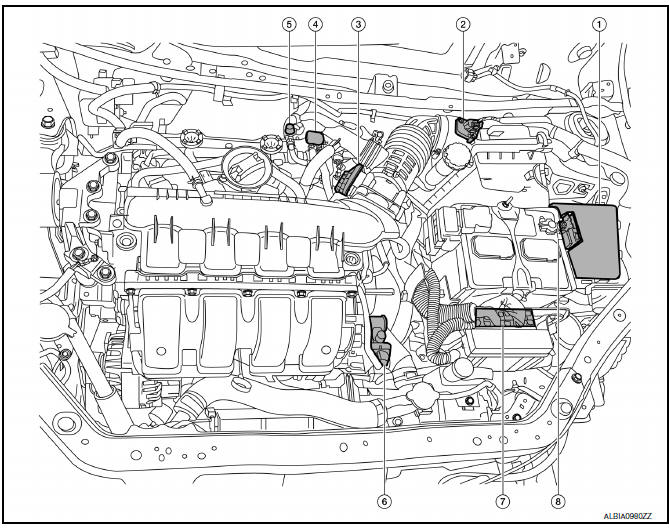
| No. | Component | Function |
| 1 | IPDM E/R | IPDM E/R control the internal relays and the actuators.
When CAN communication with ECM is impossible, IPDM E/R performs fail-safe control. With Intelligent Key System
Without Intelligent Key System
|
| 2 | Mass air flow sensor (with intake air temperature sensor) | EC-28, "Mass Air Flow Sensor (with Intake Air Temperature Sensor)" |
| 3 | Electric throttle control actuator (with built in throttle position sensor and throttle control motor) | EC-22, "Electric Throttle Control Actuator" |
| 4 | EVAP canister purge volume control solenoid valve | EC-24, "EVAP Canister Purge Volume Control Solenoid Valve" |
| 5 | EVAP service port | EVAP service port is prepared in order to perform evaporative emission system leak check. |
| 6 |
|
|
| 7 | ECM | EC-22, "ECM" |
| 8 | Battery current sensor (with battery temperature sensor) | EC-20, "Battery Current Sensor (with Battery Temperature Sensor)" |
Engine compartment
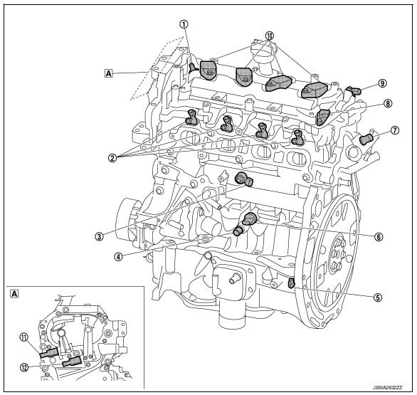
- Engine front side
| No. | Component | Function |
| 1. | PCV valve | The positive crankcase ventilation (PCV) valve is provided to conduct crankcase blow-by gas to the intake manifold. |
| 2 | Fuel injector | EC-25, "Fuel Injector" |
| 3 | Knock sensor | EC-28, "Knock Sensor" |
| 4 | Engine oil temperature sensor | EC-24, "Engine Oil Temperature Sensor" |
| 5 | Crankshaft position sensor (POS) | EC-21, "Crankshaft Position Sensor (POS)" |
| 6 | Engine oil pressure sensor | EC-23, "Engine Oil Pressure Sensor" |
| 7 | Engine coolant temperature sensor | EC-23, "Engine Coolant Temperature Sensor" |
| 8 | Camshaft position sensor (PHASE) | EC-21, "Camshaft Position Sensor (PHASE)" |
| 9 | Exhaust valve timing control position sensor | EC-25, "Exhaust Valve Timing Control Position Sensor" |
| 10 | Ignition coil (with power transistor) | EC-27, "Ignition Coil with Power Transistor" |
| 11 | Exhaust valve timing control solenoid valve | EC-25, "Exhaust Valve Timing Control Solenoid Valve" |
| 12 | Intake valve timing control solenoid valve | EC-27, "Intake Valve Timing Control Solenoid Valve" |
Exhaust compartment
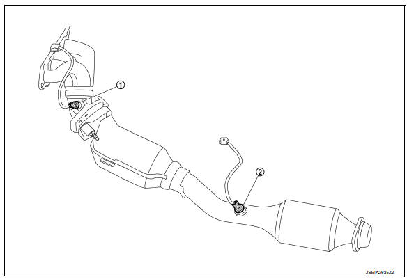
| No. | Component | Function |
| 1. | Air fuel ratio (A/F) sensor 1 | EC-19, "Air Fuel Ratio (A/F) Sensor 1" |
| 2. | Heated oxygen sensor 2 | EC-26, "Heated Oxygen Sensor 2" |
Body compartment
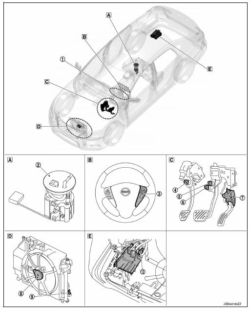
- Under the right side second seat
- On the steering wheel
- Periphery of pedals
- Radiator assembly
- Under the left side fuel tank
| No. | Component | Function |
| 1 | Combination meter | MWI-6, "METER SYSTEM : Component Description" |
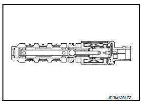
| 2 | Fuel level sensor unit, fuel filter and fuel pump assembly | EC-26, "Fuel Level Sensor Unit, Fuel Filter and Fuel Pump Assembly" |
| 3 | ASCD steering switch | EC-20, "ASCD Steering Switch" |
| 4 | Clutch pedal position switch | EC-21, "Clutch Pedal Position Switch" |
| 5 | Stop lamp switch | EC-29, "Stop Lamp Switch & Brake Pedal Position Switch" |
| 6 | Brake pedal position switch | EC-29, "Stop Lamp Switch & Brake Pedal Position Switch" |
| 7 | Accelerator pedal position sensor | EC-19, "Accelerator Pedal Position Sensor" |
| 8 | Cooling fan motor | EC-21, "Cooling Fan" |
| 9 | Refrigerant pressure sensor | EC-29, "Refrigerant Pressure Sensor" |
| 10 | EVAP control system pressure sensor | EC-25, "EVAP Control System Pressure Sensor" |
| 11 | EVAP canister | EVAP canister stores the generated fuel vapors in the sealed fuel tank to activated charcoals of EVAP canister when the engine is not operating or when refueling to the tank. |
| 12 | EVAP canister vent control valve | EC-24, "EVAP Canister Vent Control Valve" |
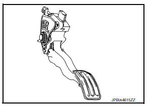
Accelerator Pedal Position Sensor
The accelerator pedal position sensor is installed on the upper end of the accelerator pedal assembly. The sensor detects the accelerator position and sends a signal to the ECM.
Accelerator pedal position sensor has two sensors. These sensors are a kind of potentiometers which transform the accelerator pedal position into output voltage, and emit the voltage signal to the ECM.
In addition, these sensors detect the opening and closing speed of the accelerator pedal and feed the voltage signals to the ECM. The ECM judges the current opening angle of the accelerator pedal from these signals and controls the throttle control motor based on these signals.
Idle position of the accelerator pedal is determined by the ECM receiving the signal from the accelerator pedal position sensor. The ECM uses this signal for the engine operation such as fuel cut.
Air Fuel Ratio (A/F) Sensor 1
DESCRIPTION
The sensor element of the A/F sensor 1 is composed an electrode layer, which transports ions. It has a heater in the element.
The sensor is capable of precise measurement = 1, but also in the lean and rich range. Together with its control electronics, the sensor outputs a clear, continuous signal throughout a wide range.
The exhaust gas components diffuse through the diffusion layer at the sensor cell. An electrode layer is applied voltage, and this current relative oxygen density in lean. Also this current relative hydrocarbon density in rich.
Therefore, the A/F sensor 1 is able to indicate air fuel ratio by this electrode layer of current. In addition, a heater is integrated in the sensor to ensure the required operating temperature of approximately 760В°C (1,400В°F).
A/F SENSOR 1 HEATER
A/F sensor 1 heater is integrated in the sensor.
The ECM performs ON/OFF duty control of the A/F sensor 1 heater corresponding to the engine operating condition to keep the temperature of A/F sensor 1 element within the specified range.
ASCD Steering Switch
ASCD steering switch has variant values of electrical resistance for each button. ECM reads voltage variation of switch, and determines which button is operated.
Battery Current Sensor (with Battery Temperature Sensor)
OUTLINE
The power generation voltage variable control enables fuel consumption to be decreased by reducing the engine load which is caused by the power generation of the generator.
Based on sensor signals, ECM judges whether or not the power generation voltage variable control is performed. When performing the power generation voltage variable control, ECM calculates the target power generation voltage based on the sensor signal. And ECM sends the calculated value as the power generation command value to IPDM E/R. For the details of the power generation voltage variable control, refer to CHG-8, "System Description".
CAUTION:
Never connect the electrical component or the ground wire directly to the battery terminal. The connection causes the malfunction of the power generation voltage variable control, and then the battery discharge may occur.
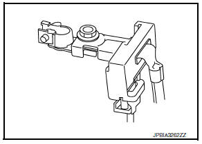
BATTERY CURRENT SENSOR
The battery current sensor is installed to the battery negative cable. The sensor measures the charging/discharging current of the battery.
Battery temperature sensor
Battery temperature sensor is integrated in battery current sensor.
The sensor measures temperature around the battery.
The electrical resistance of the thermistor decreases as temperature increases.
<Reference data>
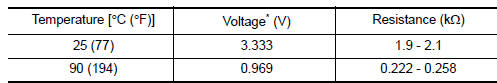
*: These data are reference values and are measured between battery temperature sensor signal terminal and sensor ground.
Camshaft Position Sensor (PHASE)
The camshaft position sensor (PHASE) senses the retraction of intake camshaft to identify a particular cylinder. The camshaft position sensor (PHASE) senses the piston position.
When the crankshaft position sensor (POS) system becomes inoperative, the camshaft position sensor (PHASE) provides various controls of engine parts instead, utilizing timing of cylinder identification signals.
The sensor consists of a permanent magnet and Hall IC.
When engine is running, the high and low parts of the teeth cause the gap with the sensor to change.
The changing gap causes the magnetic field near the sensor to change.
Due to the changing magnetic field, the voltage from the sensor changes.
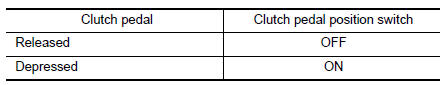
Clutch Pedal Position Switch
Stop lamp switch is installed to clutch pedal bracket. The switch detects the state of the clutch pedal and transmits an ON/OFF signal to ECM.
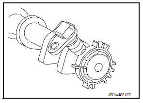
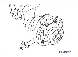
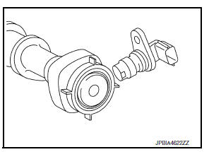
Crankshaft Position Sensor (POS)
The crankshaft position sensor (POS) is located on the oil pan facing the gear teeth (cogs) of the signal plate. It detects the fluctuation of the engine revolution.
The sensor consists of a permanent magnet and Hall IC.
When the engine is running, the high and low parts of the teeth cause the gap with the sensor to change.
The changing gap causes the magnetic field near the sensor to change.
Due to the changing magnetic field, the voltage from the sensor changes.
The ECM receives the voltage signal and detects the fluctuation of the engine revolution.
Cooling Fan
Cooling fan operates when the current flows in the cooling fan motor.
For control details, refer to EC-47, "COOLING FAN CONTROL : System Description".
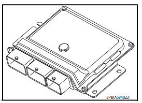
ECM
The ECM consists of a microcomputer and connectors for signal input and output and for power supply. The ECM controls the engine.
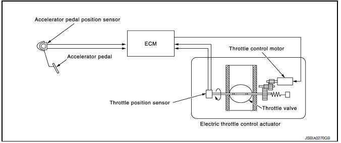
Electric Throttle Control Actuator
OUTLINE
Electric throttle control actuator consists of throttle body, throttle valve, throttle control motor and throttle position sensor.
THROTTLE CONTROL MOTOR RELAY
Power supply for the throttle control motor is provided to the ECM via throttle control motor relay. The throttle control motor relay is ON/OFF controlled by the ECM. When the ignition switch is turned ON, the ECM sends an ON signal to throttle control motor relay and battery voltage is provided to the ECM. When the ignition switch is turned OFF, the ECM sends an OFF signal to throttle control motor relay and battery voltage is not provided to the ECM.
THROTTLE CONTROL MOTOR
The throttle control motor is operated by the ECM and it opens and closes the throttle valve.
The current opening angle of the throttle valve is detected by the throttle position sensor and it provides feedback to the ECM to control the throttle control motor to make the throttle valve opening angle properly in response to driving condition.
Throttle position sensor
The throttle position sensor responds to the throttle valve movement.
The throttle position sensor has two sensors. These sensors are a kind of potentiometers which transform the throttle valve position into output voltage, and emit the voltage signal to the ECM. In addition, these sensors detect the opening and closing speed of the throttle valve and feed the voltage signals to the ECM. The ECM judges the current opening angle of the throttle valve from these signals and the ECM controls the throttle control motor to make the throttle valve opening angle properly in response to driving condition.
Engine Coolant Temperature Sensor
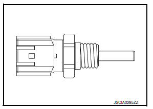
The engine coolant temperature sensor is used to detect the engine coolant temperature. The sensor modifies a voltage signal from the ECM. The modified signal returns to the ECM as the engine coolant temperature input. The sensor uses a thermistor which is sensitive to the change in temperature. The electrical resistance of the thermistor decreases as temperature increases.
<Reference data>
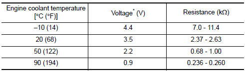
*: These data are reference values and are measured between ECM terminals.
Engine Oil Pressure Sensor
The engine oil pressure (EOP) sensor is detects engine oil pressure and transmits a voltage signal to the ECM.
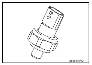
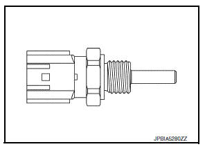
Engine Oil Temperature Sensor
The engine oil temperature sensor is used to detect the engine oil temperature. The sensor modifies a voltage signal from the ECM.
The modified signal returns to the ECM as the engine oil temperature input. The sensor uses a thermistor which is sensitive to the change in temperature. The electrical resistance of the thermistor decreases as temperature increases.
<Reference data>
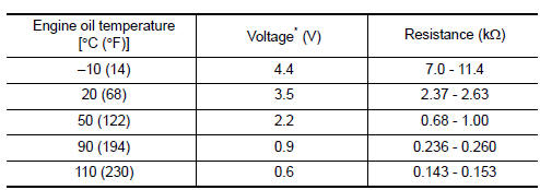
*: These data are reference values and are measured between ECM terminals.
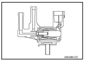
EVAP Canister Purge Volume Control Solenoid Valve
The EVAP canister purge volume control solenoid valve uses a ON/ OFF duty to control the flow rate of fuel vapor from the EVAP canister.
The EVAP canister purge volume control solenoid valve is moved by ON/OFF pulses from the ECM. The longer the ON pulse, the greater the amount of fuel vapor that will flow through the valve.
EVAP Canister Vent Control Valve
The EVAP canister vent control valve is located on the EVAP canister and is used to seal the canister vent.
This solenoid valve responds to signals from the ECM. When the ECM sends an ON signal, the coil in the solenoid valve is energized.
A plunger will then move to seal the canister vent. The ability to seal the vent is necessary for the on board diagnosis of other evaporative emission control system components.
This solenoid valve is used only for diagnosis, and usually remains opened.
When the vent is closed, under normal purge conditions, the evaporative emission control system is depressurized and allows “EVAP Control System” diagnosis.
EVAP Control System Pressure Sensor
The EVAP control system pressure sensor detects pressure in the purge line. The sensor output voltage to the ECM increases as pressure increases.
Exhaust Valve Timing Control Position Sensor
Exhaust valve timing control position sensor detects the protrusion of the signal plate installed to the exhaust camshaft front end.
This sensor signal is used for sensing a position of the exhaust camshaft.
The sensor consists of a permanent magnet and Hall IC.
When engine is running, the high and low parts of the teeth cause the gap with the sensor to change.
The changing gap causes the magnetic field near the sensor to change.
Due to the changing magnetic field, the voltage from the sensor changes.
Exhaust Valve Timing Control Solenoid Valve
Exhaust valve timing control solenoid valve is activated by ON/OFF pulse duty (ratio) signals from the ECM.
The exhaust valve timing control solenoid valve changes the oil amount and direction of flow through exhaust valve timing control unit or stops oil flow.
The longer pulse width retards valve angle.
The shorter pulse width advances valve angle.
When ON and OFF pulse widths become equal, the solenoid valve stops oil pressure flow to fix the exhaust valve angle at the control position.
Fuel Injector
The fuel injector is a small, precise solenoid valve. When the ECM supplies a ground to the fuel injector circuit, the coil in the fuel injector is energized. The energized coil pulls the ball valve back and allows fuel to flow through the fuel injector into the intake manifold.
The amount of fuel injected depends upon the injection pulse duration.
Pulse duration is the length of time the fuel injector remains open. The ECM controls the injection pulse duration based on engine fuel needs.
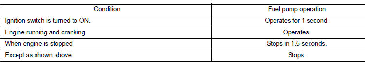
Fuel Level Sensor Unit, Fuel Filter and Fuel Pump Assembly
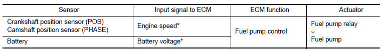
*: ECM determines the start signal status by the signals of engine speed and battery voltage.
The ECM activates the fuel pump for a few seconds after the ignition switch is turned ON to improve engine start ability. If the ECM receives a engine speed signal from the crankshaft position sensor (POS) and camshaft position sensor (PHASE), it knows that the engine is rotating, and causes the pump to operate. If the engine speed signal is not received when the ignition switch is ON, the engine stalls. The ECM stops pump operation and prevents battery discharging, thereby improving safety. The ECM does not directly drive the fuel pump. It controls the ON/OFF fuel pump relay, which in turn controls the fuel pump.
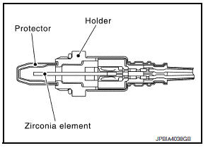
Heated Oxygen Sensor 2
DESCRIPTION
The heated oxygen sensor 2, after three way catalyst (manifold), monitors the oxygen level in the exhaust gas.
Even if switching characteristics of the air fuel ratio (A/F) sensor 1 are shifted, the air fuel ratio is controlled to stoichiometric, by the signal from the heated oxygen sensor 2.
This sensor is made of ceramic zirconia. The zirconia generates voltage from approximately 1 V in richer conditions to 0 V in leaner conditions.
Under normal conditions the heated oxygen sensor 2 is not used for engine control operation.
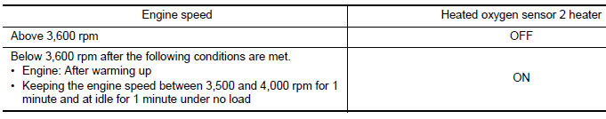
HEATED OXYGEN SENSOR 2 HEATER
Heated oxygen sensor 2 heater is integrated in the sensor.
The ECM performs ON/OFF control of the heated oxygen sensor 2 heater corresponding to the engine speed, amount of intake air and engine coolant temperature.
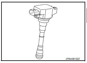
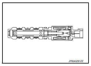
Ignition Coil with Power Transistor
The ignition signal from the ECM is sent to and amplified by the power transistor. The power transistor turns ON and OFF the ignition coil primary circuit. This ON/OFF operation induces the proper high voltage in the coil secondary circuit.
Intake Valve Timing Control Solenoid Valve
Intake valve timing control solenoid valve is activated by ON/OFF pulse duty (ratio) signals from the ECM.
The intake valve timing control solenoid valve changes the oil amount and direction of flow through intake valve timing control unit or stops oil flow.
The longer pulse width advances valve angle.
The shorter pulse width retards valve angle.
When ON and OFF pulse widths become equal, the solenoid valve stops oil pressure flow to fix the intake valve angle at the control position.
Intake Manifold Runner Control Valve
Intake manifold runner control valve is integrated to intake manifold.
Intake manifold runner control valve is mounted each port of the intake manifold and opened/closed by the intake manifold runner control valve motor.
ECM controls the intake manifold runner control valve motor, according to signals of engine speed, water temperature, etc. and stabilizes combustion by generating a strong tunmble flow.
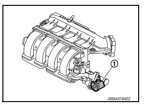
INTAKE MANIFOLD RUNNER CONTROL VALVE MOTOR
Intake manifold runner control valve motor is connected to the rear end of the valve shaft.
The motor opens or closes the valve by the output signal of the ECM.
INTAKE MANIFOLD RUNNER CONTROL VALVE POSITION SENSOR
Intake manifold runner control valve position sensor is connected to the front end of the valve shaft.
The sensor consists of valiable resister. It senses the valve shaft movement and feeds the voltage signals to the ECM.
Intake Manifold Tuning Valve
Intake manifold tuning (IMT) valve is integrated to intake manifold.
Intake manifold tuning valve consists of valve and motor.
Intake manifold tuning valve is used to control the suction passage of the intake manifold tuning system.
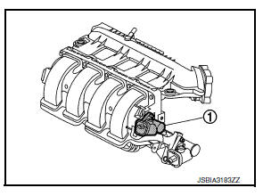
INTAKE MANIFOLD TUNING VALVE MOTOR
Intake manifold tuning valve motor is connected to the front end of the valve shaft.
The motor is operated by the ECM and it opens and closes the intake manifold tuning valve.
Knock Sensor
The knock sensor is attached to the cylinder block. It senses engine knocking using a piezoelectric element. A knocking vibration from the cylinder block is sensed as vibrational pressure. This pressure is converted into a voltage signal and sent to the ECM.
Mass Air Flow Sensor (with Intake Air Temperature Sensor)
MASS AIR FLOW SENSOR
The mass air flow sensor is placed in the stream of intake air. It measures the intake flow rate by measuring a part of the entire intake flow. The mass air flow sensor controls the temperature of the heater in sensing element to a certain amount.
The temperature distribution around the heater changes according to the increase in intake air volume. The change is detected by a thermistor and the air volume data is sent to ECM by the MAF sensor.
Intake air temperature sensor
The intake air temperature sensor is built-into mass air flow sensor. The sensor detects intake air temperature and transmits a signal to the ECM.
The temperature sensing unit uses a thermistor which is sensitive to the change in temperature.
<Reference data>
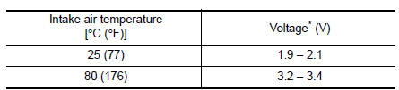
*: These data are reference values on the diagnosis tool.
Park/Neutral Position Switch
Park/Neutral Position Switch is installed to manual transaxle. The switch detects the neutral position and transmits a voltage signal.
Refrigerant Pressure Sensor
The refrigerant pressure sensor is installed at the condenser of the air conditioner system. The sensor uses an electrostatic volume pressure transducer to convert refrigerant pressure to voltage. The voltage signal is sent to ECM, and ECM controls cooling fan system.
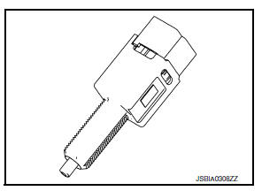
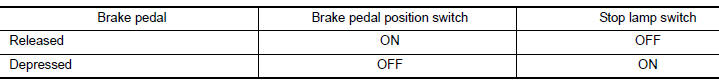
Stop Lamp Switch & Brake Pedal Position Switch
Stop lamp switch and brake pedal position switch are installed to brake pedal bracket.
ECM detects the state of the brake pedal by those two types of input (ON/OFF signal).
Transmission Range Switch
Transmittion Range Switch is installed to automatic transmission and CVT transaxle. The switch detects the state of the gear position (N range and P range) and transmits a voltage signal to ECM.

 Structure and operation
Positive Crankcase Ventilation
This system returns blow-by gas to the intake manifold.
The positive crankcase ventilation (PCV) valve is provided to conduct crankcase
blow-by gas to the inta ...
Other materials:
B0097 Rear side air bag satellite sensor RH
Description
DTC B0097 REAR SATELLITE SENSOR RH
The rear side air bag satellite sensor RH is wired to the air bag diagnosis
sensor unit. The air bag diagnosis
sensor unit will monitor the rear side air bag satellite sensor RH for internal
failures and its circuits for communication
errors.
P ...
P0520 EOP System
DTC Logic
DTC DETECTION LOGIC
DTC No.
CONSULT screen terms
(Trouble diagnosis content)
DTC detecting condition
Possible cause
P0520
EOP SENSOR/SWITCH
(Engine oil pressure sensor/
switch circuit)
ECM detects the following status continuously
for 5 seconds ...
P0011 IVT control
DTC Logic
DTC DETECTION LOGIC
NOTE:
If DTC P0011 is displayed with DTC P0075, first perform the trouble
diagnosis for EC-180, "DTC Logic".
DTC No.
CONSULT screen terms
(Trouble diagnosis content)
DTC detecting condition
Possible cause
P0011
INT/V TIM CO ...
