Nissan Sentra Service Manual: C1120, C1122, C1124, C1126 ABS In valve system
DTC Logic
Dtc detection logic
| DTC | Display Item | Malfunction detected condition | Possible causes |
| C1120 | FR LH IN ABS SOL | When a malfunction is detected in front LH ABS IN valve. |
|
| C1122 | FR RH IN ABS SOL | When a malfunction is detected in front RH ABS IN valve. | |
| C1124 | RR LH IN ABS SOL | When a malfunction is detected in rear LH ABS IN valve. | |
| C1126 | RR RH IN ABS SOL | When a malfunction is detected in rear RH ABS IN valve. |
DTC CONFIRMATION PROCEDURE
1.CHECK SELF DIAGNOSTIC RESULT
 With CONSULT
-
Turn ignition switch ON.
-
Perform self diagnostic result.
Is DTC C1120, C1122, C1124 or C1126 detected? YES >> Proceed to diagnosis procedure. Refer to BRC-72, "Diagnosis Procedure".
NO >> Inspection End.
Diagnosis Procedure
Regarding Wiring Diagram information, refer to BRC-44, "Wiring Diagram".
1.CONNECTOR INSPECTION
-
Turn ignition switch OFF.
-
Disconnect ABS actuator and electric unit (control unit) connector.
-
Check connector and terminals for deformation, disconnection, looseness or damage.
Is the inspection result normal? YES >> GO TO 2.
NO >> Repair or replace as necessary.
2.Check ABS Actuator and electric unit (control unit) battery power supply
Check voltage between ABS actuator and electric unit (control unit) connector E33 terminal 25 and ground.
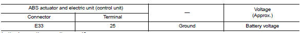
Is the inspection result normal? YES >> GO TO 3.
NO >> Repair or replace malfunctioning components.
3.Check ABS actuator and electric unit (control unit) ground circuit
Check continuity between ABS actuator and electric unit (control unit) connector E33 terminals 13, 38 and ground.
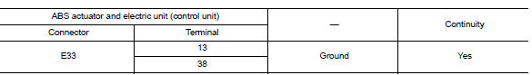
Is the inspection result normal? YES >> Replace ABS actuator and electric unit (control unit). Refer to BRC-110, "Removal and Installation".
NO >> Repair or replace malfunctioning components.
 C1116 Stop lamp switch
DTC Logic
DTC DETECTION LOGIC
DTC
Display item
Malfunction detected condition
Possible cause
C1116
STOP LAMP SW
When stop lamp switch circuit is open.
Harn ...
 C1121, C1123, C1125, C1127 ABS OUT Valve system
DTC Logic
DTC DETECTION LOGIC
DTC DETECTION LOGIC
Display Item
Malfunction detected condition
Possible causes
C1121
FR LH OUT ABS SOL
When a malfunction is detected i ...
Other materials:
Service data and specifications
(sds)
Periodical Maintenance Specification
ENGINE COOLANT CAPACITY (APPROXIMATE)
Radiator
Thermostat
Water Control Valve
...
Application Download
Once connected, the NissanConnect™ App will
search your phone to determine which compatible
applications are currently installed. The user
will then choose which apps they want to bring
into their vehicle from the list of apps within the
“Manage My Apps” section of the NissanConnect
™ ...
Unit removal and installation
TRANSMISSION ASSEMBLY
Exploded View
Transaxle assembly
O-ring
CVT fluid charging pipe
CVT fluid charging pipe cap
Tightening must be done following the installation procedure. Refer to
TM-283, "Removal and Installation".
: Always replace after every
disassemb ...
