Nissan Sentra B18 (2020-2025) Service Manual: Front Suspension :: Removal and Installation
Front Coil Spring and Strut. Exploded View
Exploded View
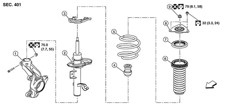
|
1. |
Steering knuckle |
2. |
Strut |
3. |
Lower rubber seat |
|
4. |
Bound bumper |
5. |
Coil spring |
6. |
Dust cover |
|
7. |
Mounting bearing |
8. |
Mounting insulator |
9. |
Piston rod lock nut |
|
|
Front |
Removal and Installation
Removal and Installation
REMOVAL
Remove the wheel and tire using power tool. Refer to Exploded View.
Remove the lock plate from the front coil spring and strut and reposition the brake hose. Refer to Exploded View.
Separate the stabilizer connecting rod from the front coil spring and strut. Refer to Exploded View.
Remove the wheel sensor bolt. Position the wheel sensor and the wheel sensor harness aside. Refer to Removal and Installation.
Remove the cotter pin from the drive shaft.
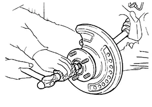
Using a
piece of wood and a suitable tool, tap on the lock nut to disengage
the drive shaft from the wheel hub and bearing.
CAUTION:
-
Do not place the drive shaft joint at an extreme angle. Be careful not to over extend the slide joint.
-
Do not allow the drive shaft to hang without support.

Use a suitable puller if drive shaft cannot be separated from the wheel hub and bearing.
Loosen the wheel hub lock nut using power tool.
Remove the wheel hub lock nut. Refer to Exploded View
Use a jack to support the transverse link and the steering knuckle.
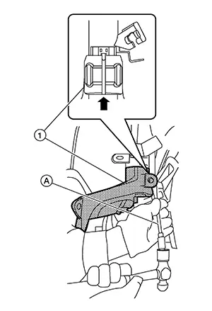
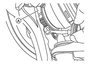
Remove upper pinch bolt and nut from steering knuckle.
Open the
slot using a suitable tool (A). Separate the steering knuckle (1)
from the front coil spring and strut.
CAUTION:
Do not drop steering knuckle.
Remove the cowl top cover. Refer to Removal and Installation.
Remove
mounting bolts (A) of mounting insulator, and then remove strut
assembly. 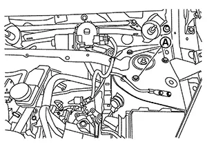
CAUTION:
Do not hit or damage the strut piston rod.
Inspect the components. Refer to Inspection.
INSTALLATION
Installation is in the reverse order of removal.
CAUTION:
-
Do not reuse piston rod lock nut.
-
Do not reuse the lower strut nuts.
-
Install the front coil spring and strut (1) in the Nissan Sentra vehicle as shown.
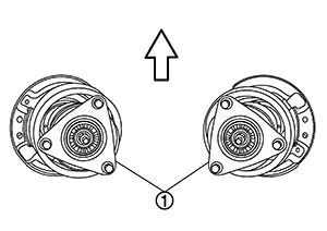

: Nissan Sentra Vehicle front
-
Perform the final tightening of the bolts and nuts under unladen conditions with the tires on level ground.
-
Complete the inspection. Refer to Inspection.
-
After replacing the strut, always follow the disposal procedure to discard the old strut. Refer to Disposal.
Transverse Link. Exploded View
Exploded View
Exploded View
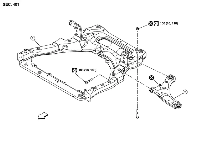
|
1. |
Front suspension member |
2. |
Transverse link |
|
Front |
Removal and Installation
Removal and Installation
REMOVAL
Remove the wheel and tire using power tool. Refer to Exploded View.
Remove the nut and bolt from the lower ball joint. Disconnect the transverse link from steering knuckle. Refer to Exploded View.
Remove the nuts and bolts and disconnect the transverse link from the suspension member.
Inspect the components. Refer to Inspection.
INSTALLATION
Installation is in the reverse order of removal.
CAUTION:
Do not reuse the transverse link nuts.
-
Perform the final tightening of the nuts and bolts under unladen conditions with the tires on level ground.
-
Complete the inspection. Refer to Inspection.
Inspection
Inspection
INSPECTION AFTER REMOVAL
Check the following items, and replace the parts if necessary.
Transverse Link
-
Check the transverse link for deformation, cracks or damage.
-
Check the bushing for complete separation. (If completely separated, inner metal can be pulled out from transverse link.)
-
Check the ball joint boot for cracks or other damage, and also for grease leaks.
Swing Torque
Move the ball joint at least ten times by hand to check for smooth movement with no binding.
Hook the
Tool (A) on the on ball joint (B). Confirm the measurement value is
within specifications when the ball joint begins moving. 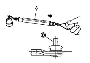
|
Tool number |
:  —  (NI-44372) |
|
Swing torque |
: Refer to Ball Joint. |
|
Measurement on spring balance |
: Refer to Ball Joint. |
-
If swing torque exceeds standard range, replace the transverse link.
Axial End Play
Move the ball joint at least ten times by hand to check for smooth movement.
Move the
tip of the ball joint in the axial direction to check for
looseness. Note:
If there is axial end play, replace transverse link assembly.
INSPECTION AFTER INSTALLATION
Check the neutral position of the steering angle sensor. Refer to Description.
Check the wheel alignment. Refer to Inspection.
Front Stabilizer. Exploded View
Exploded View
Exploded View
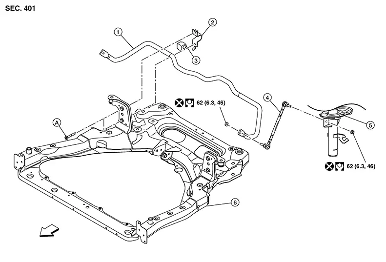
|
1. |
Stabilizer bar |
2. |
Stabilizer clamp |
3. |
Stabilizer bushing |
|
4. |
Stabilizer connecting rod |
5. |
Front strut |
6. |
Front suspension member |
|
A. |
Refer to Removal and Installation. |
|
Front |

Removal and Installation
Removal and Installation
REMOVAL
Remove the wheel and tire using power tool. Refer to Removal and Installation.
Remove the nut and disconnect the stabilizer connecting rod from the stabilizer bar.
Remove the front suspension member. Refer to Removal and Installation.
Remove
mounting bolts (A) from stabilizer clamps. 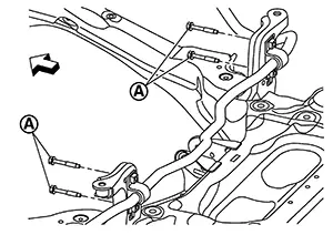
|
|
: Nissan Sentra Vehicle front |
Remove the stabilizer clamps.
Remove the stabilizer bushings.
Remove the stabilizer bar.
Inspect the components. Refer to Inspection.
INSTALLATION
Installation is in the reverse order of removal.
-
Align the stabilizer clamp tab (A) with front suspension member hole (B).
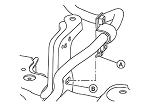
-
Torque bolts to specification in the sequence shown.
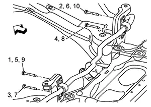
Manual screwing 2 pitch minimum
: 1,2 Temporary tightening
: 3-6
Final tightening (Specified torque)
: 7-10
: Front
-
To connect the stabilizer connecting rod (1), tighten the nut while holding the hexagonal part (A) on the stabilizer connecting rod.
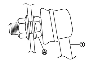
CAUTION:
Do not reuse stabilizer connecting rod nuts.
-
Perform the final tightening of the nuts and bolts under unladen conditions with the tires on level ground.
-
Complete the inspection. Refer to Inspection.
Inspection
Inspection
INSPECTION AFTER REMOVAL
Check the stabilizer bar, the stabilizer connecting rods, the stabilizer bushings, and the stabilizer clamps for deformation, cracks or damage. Replace components if necessary.
INSPECTION AFTER INSTALLATION
Check the neutral position of the steering angle sensor. Refer to Description.
Check the wheel alignment. Refer to Inspection.
Steering Knuckle. Exploded View
Exploded View
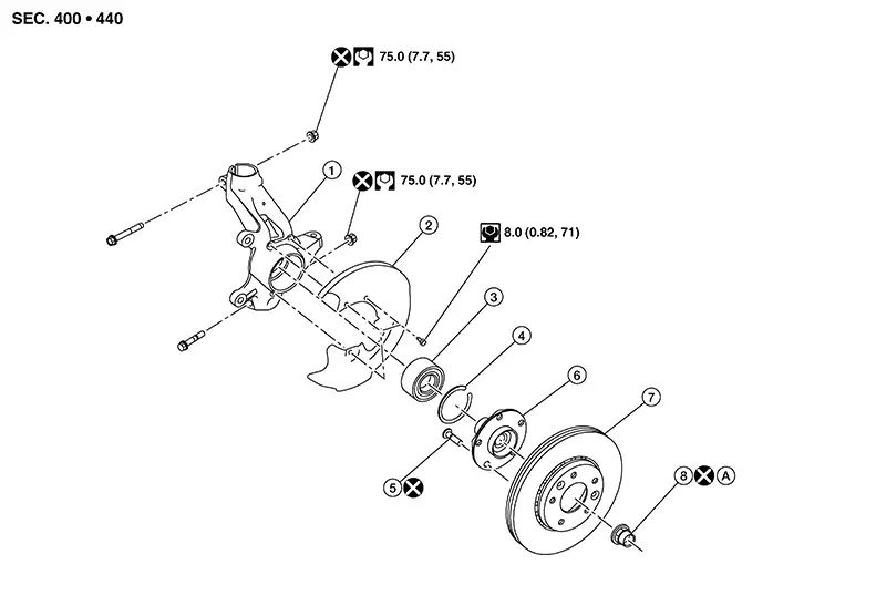
|
1. |
Steering knuckle |
2. |
Splash guard |
3. |
Wheel bearing |
|
4. |
Snap ring |
5. |
Hub bolt |
6. |
Wheel hub |
|
7. |
Disc rotor |
8. |
Wheel hub lock nut |
A. |
Refer to Removal and Installation. |
Removal and Installation
Removal and Installation
REMOVAL
For M/T models, drain the M/T oil. Refer to Draining.
Remove disc brake rotor. Refer to Removal and Installation.
CAUTION:
Do not depress the brake pedal while the brake caliper is removed.
Remove the wheel sensor bolt. Position the wheel sensor and the wheel sensor harness aside. Refer to Removal and Installation.
CAUTION:
Do not pull or twist the harness when removing.
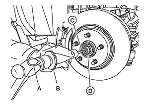
Using hammer (A) and Tool (B) release staked area (C) of wheel hub lock nut (D).
|
Tool number (B) |
: (NI-52982) |
Visually verify that staked area
(A) of wheel hub lock nut (B) is completely released from front drive
shaft (1) or damage to drive shaft can occur.
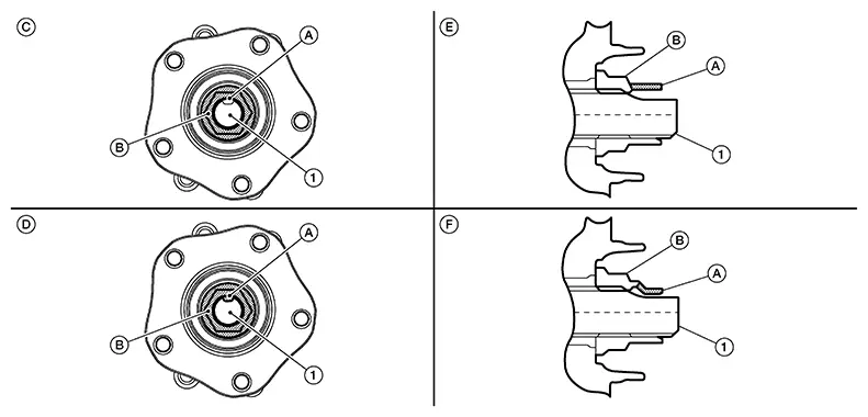
|
(C) |
: Fully released |
|
(D) |
: Not fully released |
|
(E) |
: Fully released (sectional view) |
|
(F) |
: Not fully released (sectional view) |
Warning:
To avoid risk of death or severe personal injury:
-
Be sure that staked area of wheel hub lock nut is fully released or damage to drive shaft can occur.
-
Do not damage front drive shaft threads.
Hold the wheel hub and bearing using
Tool (A). Loosen the wheel hub lock nut.
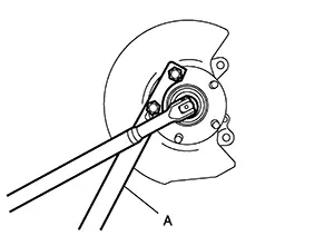
|
Tool (A) number |
: KV4014000 ( — ) |
Warning:
To avoid risk of death or severe personal injury:
-
Do not use power tool.
-
Do not damage front drive shaft threads.
-
Do not reuse drive shaft lock nut.
-
When loosening lock nut, if it does not turn smoothly, verify that staked area is completely released.
Using a piece of wood and a suitable
tool, tap on the wheel hub lock nut to disengage the drive shaft from
the wheel hub and bearing.
CAUTION:
-
Do not place the drive shaft joint at an extreme angle. Also be careful not to overextend slide joint.
-
Do not allow the drive shaft to hang down without support.
Use a suitable puller if the drive shaft cannot be separated from the wheel hub and bearing even after performing the above procedure.
Remove the wheel hub lock nut.
Remove the nut and bolt from the lower ball joint. Disconnect the steering knuckle from the transverse link.
Remove the drive shaft from the wheel hub and bearing.
Remove the wheel hub and bearing from the steering knuckle. Refer to Removal and Installation.
Remove upper pinch bolt and nut from steering knuckle.
CAUTION:
Do not reuse the upper pinch nut.
Remove the lower nut and bolt from the steering knuckle. Separate the transverse link from the steering knuckle. Refer to Exploded View.
Remove the nut and separate the outer socket from the steering knuckle. Refer to Exploded View.
Separate steering knuckle from coil spring and strut. Refer to Removal and Installation.
Remove the steering knuckle.
Perform inspection after removal. Refer to Inspection.
INSTALLATION
Installation is in the reverse order of the removal.
CAUTION:
-
Do not reuse upper pinch nut.
-
Do not reuse the lower strut pinch nut.
-
Apply a moderate coat of paste [service parts (440037S000)] to bearing surface (A) as shown.
 Note:
Note:
Always check with the Parts Department for the latest parts information.
-
Tighten wheel hub lock nut to specification. Refer to Exploded View.
-
Perform inspection after installation. Refer to Inspection.
Inspection
Inspection
INSPECTION AFTER REMOVAL
Check the following items, and replace the part if necessary.
-
Check components for deformation, cracks, and other damage.
-
Check boots of transverse link and steering outer socket ball joint for breakage, axial end play, and swing torque.
-
Transverse link: Refer to Inspection.
-
Steering outer socket: Refer to Inspection.
-
INSPECTION AFTER INSTALLATION
Check the wheel sensor harness to be sure the connectors are fully seated.
Check the wheel alignment. Refer to Inspection.
Other materials:
Rear Axle. Precaution. Precautions. Precaution for Supplemental Restraint System (srs) "air Bag" and "seat Belt Pre-Tensioner"
Precautions. Precaution for Supplemental Restraint System (srs) "air Bag" and "seat Belt Pre-Tensioner"
Precaution for Supplemental Restraint System (srs) "air Bag" and "seat Belt Pre-Tensioner"
Precaution for Supplemental Restraint System (SRS) "AIR BAG" an ...
C1f5f-49 Distance Sensor
Dtc Description
DTC Description
DTC DETECTION LOGIC
DTC
CONSULT screen terms
(Trouble diagnosis
content)
DTC detection
conditi ...
Preparation. Preparation
Preparation
Engine Control System : Special Service Tool
ENGINE CONTROL SYSTEM : Special Service Tool
The actual shape of the tools may differ from those
illustrated here.
Tool number
(TechMate No.)
To ...