Nissan Sentra B18 (2020-2025) Service Manual: Input Shaft and Gear
Exploded View
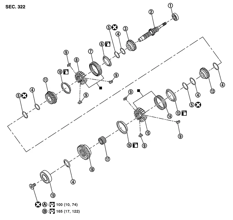
Exploded View
|
1. |
Input shaft front bearing |
2. |
Input shaft |
3. |
3rd input gear |
|
4. |
Spacer |
5. |
Snap ring |
6. |
3rd baulk ring |
|
7. |
3rd-4th coupling sleeve |
8. |
3rd-4th synchronizer hub |
9. |
Insert key |
|
10. |
4th baulk ring |
11. |
4th input gear |
12. |
5th input gear |
|
13. |
5th baulk ring |
14. |
5th-6th coupling sleeve |
15. |
5th-6th synchronizer hub |
|
16. |
6th baulk ring |
17. |
Needle bearing |
18. |
6th input gear |
|
19. |
Input shaft rear bearing |
A. |
First step |
B. |
Final step |
Disassembly
Disassembly
CAUTION:
-
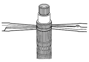
Fix input shaft in a vise with back plate, and then remove gears and snap rings.
-
For removal of snap ring, set snap ring pliers and flat pliers at both sides of snap ring. While expanding snap ring with snap ring pliers, move snap ring with flat pliers.
-
Disassemble gear components putting direction marks on the parts that do not affect any functions.
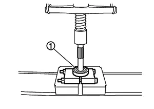
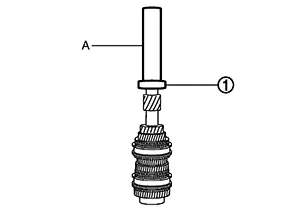
Remove
input shaft rear bearing bolt (1), using Tool (A).
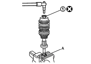
CAUTION:
Do not reuse rear bearing bolt.
|
Tool number (A) |
: KV32300QAM (  —  ) |
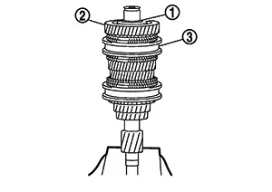
Remove
input shaft rear bearing (1) with the following procedure.
 Set a
suitable tool to input shaft rear bearing.
Remove input shaft rear bearing
using suitable tool (A).
Set a
suitable tool to input shaft rear bearing.
Remove input shaft rear bearing
using suitable tool (A).
Remove
spacer (1), 6th input gear (2), needle bearing, 6th baulk ring, and
5th-6th synchronizer hub assembly (3).
Remove insert keys and 5th-6th coupling sleeve from 5th-6th synchronizer hub.
Remove snap
ring (1).
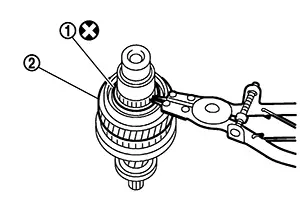
CAUTION:
Do not reuse snap ring.
Remove spacer, 5th baulk ring, 5th input gear (2), and spacer.
Remove snap
ring (1).
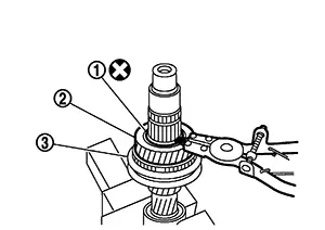
CAUTION:
Do not reuse snap ring.
Remove spacer, 4th input gear (2), 4th baulk ring, and 3rd-4th synchronizer hub assembly (3).
Remove insert keys and 3rd-4th coupling sleeve from 3rd-4th synchronizer hub.
Remove snap ring (1).
CAUTION:
Do not reuse snap ring.

Remove spacer, 3rd baulk ring, and 3rd input gear (2).
Set a
suitable tool to input shaft front bearing (1), and then remove
input shaft front bearing.
Assembly
Assembly
Assembly is in the reverse order of disassembly.
CAUTION:
-
Replace transaxle assembly when replacing input shaft.
-
For installation of snap ring, set snap ring pliers and flat pliers at both sides of snap ring. While expanding snap ring with snap ring pliers, move snap ring with flat pliers.
-
Do not reuse snap ring.
-
Check that snap ring is securely installed in a groove.
-
Replace 3rd-4th coupling sleeve and 3rd-4th synchronizer hub as a set.
-
Replace 5th-6th coupling sleeve and 5th-6th synchronizer hub as a set.
-
Be careful to install 3rd-4th synchronizer hub according to the specified direction.
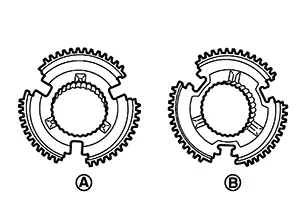
(A)
: 3rd input gear side
(B)
: 4th input gear side
-
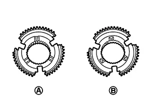
Be careful to install 5th-6th synchronizer hub according to the specified direction.
(A)
: 5th input gear side
(B)
: 6th input gear side
-
Install input shaft front bearing (1) using a suitable tool (A).
-
Install input shaft rear bearing (1) using a suitable tool (A) and Tool (B).
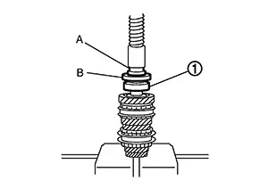
Tool number
: ST36720030 (  —  )
-
Apply gear oil to 3rd baulk ring, 4th baulk ring, 5th baulk ring, and 6th baulk ring.
-
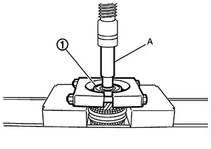
Install input shaft rear bearing bolt (1), as per the following procedure.
CAUTION:
Follow the procedures. Otherwise it may cause a transaxle malfunction.
Do not reuse rear bearing bolt.
Fix the Tool (A) in a vise and set input shaft assembly.
|
Tool number |
: KV32300QAM (  —  ) |
Install input shaft rear bearing bolt and tighten it to the specified torque of the first step.
Loosen input shaft rear bearing bolt by a half turn.
Tighten input shaft rear bearing bolt to the specified torque of the final step.
Inspection
Inspection
Input Shaft and Gear
Check the following items and replace if necessary.
Damage, peeling, bend, uneven wear, and distortion of shaft.
Excessive
wear, damage, and peeling of gear. 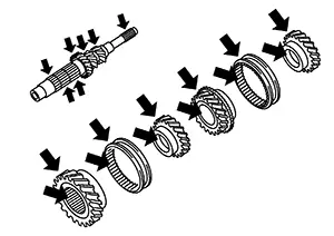
INSPECTION AFTER DISASSEMBLY
Synchronizer Hub and Coupling Sleeve
Check the following items and replace if necessary.
-
Breakage, damage, and unusual wear on contact surface of coupling sleeve, synchronizer hub, and insert key.
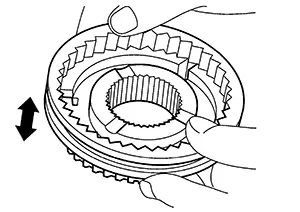
-
Coupling sleeve and synchronizer hub move smoothly.
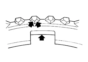
Baulk Ring
Check contact surface of baulk ring cam and insert key for excessive wear, uneven wear, bend, and damage. Replace if necessary.
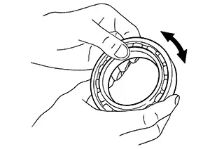
Bearing
Check bearing for damage and uneven rotation. Replace if necessary.
Other materials:
Handling Precaution
Precaution for Idle Start/stop System
Precaution for Idle Start/Stop System
PRECAUTIONS FOR IDLE START/STOP SYSTEM OPERATION
The operation of the idle start/stop system system needs to
satisfy various conditions. For details of the conditions, refer to System Description.
The idle start ...
P01f0 Engine Coolant Temperature
Dtc Description
DTC Description
DTC DETECTION LOGIC
DTC
CONSULT screen terms
(Trouble diagnosis
content)
DTC detection
condition
...
P1217 Engine Over Temperature
Dtc Description
DTC Description
ECM controls cooling fan to the maximum speed when receives the
signal abnormality of each sensor, CAN and IPDM E/R, and severed wire short
circuit abnormality.
If the cooling fan or another component in the cooling system
malfunctions, engine coola ...