Nissan Sentra B18 (2020-2025) Service Manual: Mainshaft and Gear
Exploded View
Exploded View
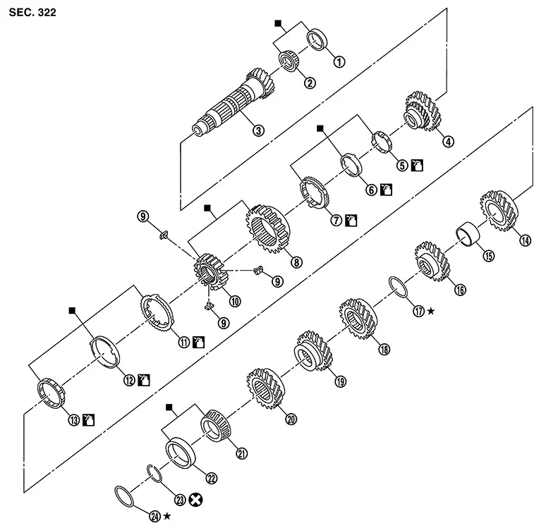
|
1. |
Mainshaft front bearing outer race |
2. |
Mainshaft front bearing inner race |
3. |
Mainshaft |
|
4. |
1st main gear |
5. |
1st inner baulk ring |
6. |
1st synchronizer cone |
|
7. |
1st outer baulk ring |
8. |
1st-2nd coupling sleeve |
9. |
Insert key |
|
10. |
1st-2nd synchronizer hub |
11. |
2nd outer baulk ring |
12. |
2nd synchronizer cone |
|
13. |
2nd inner baulk ring |
14. |
2nd main gear |
15. |
Bushing |
|
16. |
3rd main gear |
17. |
Mainshaft adjusting shim |
18. |
4th main gear |
|
19. |
5th main gear |
20. |
6th main gear |
21. |
Mainshaft rear bearing inner race |
|
22. |
Mainshaft rear bearing outer race |
23. |
Snap ring |
24. |
Mainshaft rear bearing adjusting shim |
Disassembly
Disassembly
CAUTION:
-
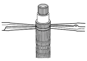
Fix mainshaft in a vise with back plate, and then remove gears and snap rings.
-
For removal of snap ring, set snap ring pliers and flat pliers at both sides of snap ring. While expanding snap ring with snap ring pliers, move snap ring with flat pliers.
-
Disassemble gear components putting direction marks on the parts that never affect any functions.
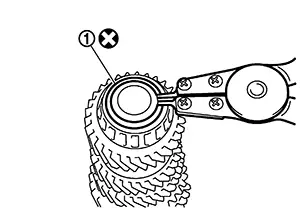
Remove snap ring (1).
CAUTION:
Do not reuse snap ring.
Remove 6th
main gear (1) and mainshaft rear bearing inner race (2), with the
following procedure. 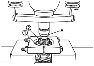 Set a
suitable tool to 6th main gear. Remove mainshaft rear bearing inner
race and 6th main gear, using Tool (A).
Set a
suitable tool to 6th main gear. Remove mainshaft rear bearing inner
race and 6th main gear, using Tool (A).
|
Tool number |
: ST33052000 ( — ) |
Remove 4th
main gear (1) and 5th main gear (2) with the following
procedure. 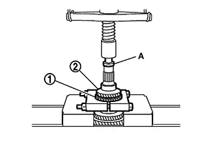 Set a
suitable tool to 4th main gear. Remove 5th main gear and 4th main
gear, using Tool (A).
Set a
suitable tool to 4th main gear. Remove 5th main gear and 4th main
gear, using Tool (A).
|
Tool number |
: ST33052000 ( — ) |
Remove mainshaft adjusting shim.
Remove 1st
main gear (1), 1st-2nd synchronizer hub assembly (2), 2nd main gear
(3), and 3rd main gear (4) with the following procedure. 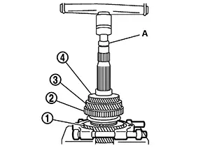 Set a
suitable tool to 1st main gear. Remove 3rd main gear, busing, 2nd
main gear, 2nd inner baulk ring, 2nd synchronizer cone, 2nd outer
baulk ring, 1st-2nd synchronizer hub assembly, 1st outer baulk
ring, 1st synchronizer cone, 1st inner baulk ring, and 1st main
gear using Tool (A).
Set a
suitable tool to 1st main gear. Remove 3rd main gear, busing, 2nd
main gear, 2nd inner baulk ring, 2nd synchronizer cone, 2nd outer
baulk ring, 1st-2nd synchronizer hub assembly, 1st outer baulk
ring, 1st synchronizer cone, 1st inner baulk ring, and 1st main
gear using Tool (A).
|
Tool number |
: ST33052000 ( — ) |
Remove
mainshaft front bearing inner race (1) with the following
procedure. 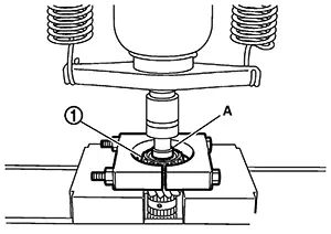 Set a
suitable tool to mainshaft front bearing inner race. Remove mainshaft front bearing inner
race using Tool (A).
Set a
suitable tool to mainshaft front bearing inner race. Remove mainshaft front bearing inner
race using Tool (A).
|
Tool number |
: ST33052000 ( — ) |
Assembly
Assembly
CAUTION:
-
Select mainshaft rear bearing adjusting shim, as per the following procedure when replacing mainshaft adjusting shim, 6th main gear, 5th main gear, or 4th main gear.
-
Replace mainshaft adjusting shim.
-
If new mainshaft adjusting shim is thinner than previous one, offset the thickness difference by selecting thicker mainshaft rear bearing adjusting shim.
-
If new mainshaft adjusting shim is thicker than previous one, offset the thickness difference by selecting thinner mainshaft rear bearing adjusting shim.
-
-
Replace 6th main gear, 5th main gear, or 4th main gear.
-
Measure the thickness of the main gear used before and the new main gear
-
Increase the thickness of the mainshaft rear bearing adjusting shim, if the difference is smaller than 0.025 mm (0.0010 in).
-
-
-
Replace transaxle assembly when replacing mainshaft.
-
For installation of snap ring, set snap ring pliers and flat pliers at both sides of snap ring. While expanding snap ring with snap ring pliers, move snap ring with flat pliers.
-
Do not reuse snap ring.
Install
mainshaft front bearing inner race (1) using Tool (A).
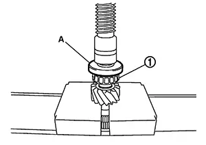
CAUTION:
Replace mainshaft front bearing outer race and mainshaft front bearing inner race as a set.
Do not reuse mainshaft front bearing inner or outer race.
|
Tool number |
: ST36720030 ( — ) |
Apply gear oil to 1st inner baulk ring, 1st synchronizer cone, 1st outer baulk ring, 2nd inner baulk ring, 2nd synchronizer cone, and 2nd outer baulk ring.
CAUTION:
-
Replace 1st inner baulk ring, 1st synchronizer cone, and 1st outer baulk ring as a set.
-
Replace 2nd inner baulk ring, 2nd synchronizer cone, and 2nd outer baulk ring as a set.
Install insert keys and 1st-2nd coupling sleeve to 1st-2nd synchronizer hub.
CAUTION:
Replace 1st-2nd synchronizer hub and 1st-2nd coupling sleeve as a set.
Install 1st
main gear (1), 1st inner baulk ring, 1st synchronizer cone, 1st
outer baulk ring, 1st-2nd synchronizer hub assembly (2), 2nd inner
baulk ring, 2nd synchronizer cone, and 2nd outer baulk ring.
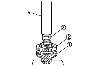
Install bushing (3) using Tool (A).
|
Tool number |
: ST32102700 ( — ) |
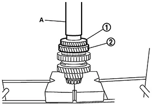
Install 3rd main gear (1) and 2nd main gear (2) using Tool (A).
|
Tool number |
: KV32102700 ( — ) |
Measure
dimension (L) as shown in the figure. Select mainshaft adjusting
shim (1) according to the following list, and then install it to
mainshaft.
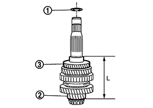
|
(2) |
: Mainshaft |
|
(3) |
: 3rd main gear |
|
Dimension (L) |
Mainshaft adjusting shim thickness |
|---|---|
|
147.690 – 147.666 (5.8146 – 5.8136) |
1.500 (0.0591) |
|
147.665 – 147.641 (5.8136 – 5.8126) |
1.525 (0.0600) |
|
147.640 – 147.616 (5.8126 – 5.8116) |
1.550 (0.0610) |
|
147.615 – 147.591 (5.8116 – 5.8107) |
1.575 (0.0620) |
|
147.590 – 147.566 (5.8106 – 5.8097) |
1.600 (0.0630) |
|
147.565 – 147.541 (5.8096 – 5.8087) |
1.625 (0.0640) |
|
147.540 – 147.516 (5.8086 – 5.8077) |
1.650 (0.0650) |
|
147.515 – 147.491 (5.8077 – 5.8067) |
1.675 (0.0659) |
|
147.490 – 147.466 (5.8067 – 5.8057) |
1.700 (0.0669) |
|
147.465 – 147.441 (5.8057 – 5.8048) |
1.725 (0.0679) |
|
147.440 – 147.416 (5.8047 – 5.8038) |
1.750 (0.0689) |
|
147.415 – 147.391 (5.8037 – 5.8028) |
1.775 (0.0699) |
Install 4th main gear (1) using Tool (A).
|
Tool number |
: KV32102700 ( — ) |
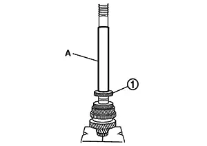
Install 5th main gear (1) using Tool (A).
|
Tool number |
: KV32102700 ( — ) |
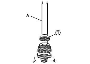
Install 6th
main gear (1) using Tool (A).
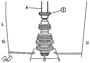
|
Tool number |
: KV32102700 ( — ) |
Install
mainshaft rear bearing inner race (1) using Tool (A).
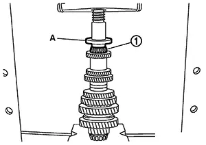
CAUTION:
Replace mainshaft rear bearing inner race and mainshaft rear bearing outer race as a set.
|
Tool number |
: ST30901000 (NI-26010-01) |
Install snap ring.
CAUTION:
Do not reuse snap ring.
Inspection
Inspection
Mainshaft and Gear
Check the following items and replace if necessary.
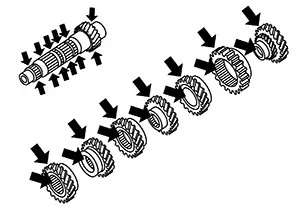
-
Damage, peeling, bend, uneven wear, and distortion of shaft.
-
Excessive wear, damage, and peeling of gear.
INSPECTION AFTER DISASSEMBLY
Synchronizer Hub and Coupling Sleeve
Check the following items and replace if necessary.
Breakage, damage, and unusual wear on contact surface of coupling sleeve, synchronizer hub, and insert key.
Coupling
sleeve and synchronizer hub move smoothly. 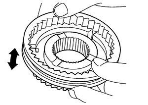
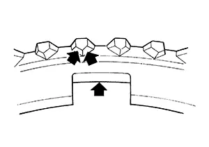
Baulk Ring
Check contact surface of baulk ring cam and insert key for excessive wear, uneven wear, bend, and damage. Replace if necessary.
Bearing
Check bearing for damage and uneven rotation. Replace if necessary.
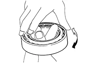
CAUTION:
-
Replace mainshaft front bearing outer race and mainshaft front bearing inner race as a set.
-
Replace mainshaft rear bearing inner race and mainshaft rear bearing outer race as a set.
Other materials:
Seat. Preparation
Preparation
Special Service Tool
Special Service Tool
The actual shape of the tools may differ from those
illustrated here.
Tool number
(TechMate No.)
Tool name
...
Periodic Maintenance. Cvt Fluid
Cvt Fluid
Inspection
Inspection
FLUID LEAKAGE
Check transaxle surrounding area (oil
seal and plug etc.) for fluid leakage.
If transaxle appears to have oil
seepage or a leak, follow the steps below to assist in a correct
diagnosis.
...
Low Tire Pressure Location Indicator Does Not Display
Symptom Description
Symptom Description
When there is low tire pressure, the low tire
location indicator does not display even though the low tire
pressure warning lamp turns ON.
Diagnosis Procedure
Diagnosis Procedure
Note:
The Signal Tech II Tool [– (NI-50190)] can be used
to ...