Nissan Sentra B18 (2020-2025) Service Manual: Transaxle Assembly
Exploded View
Exploded View
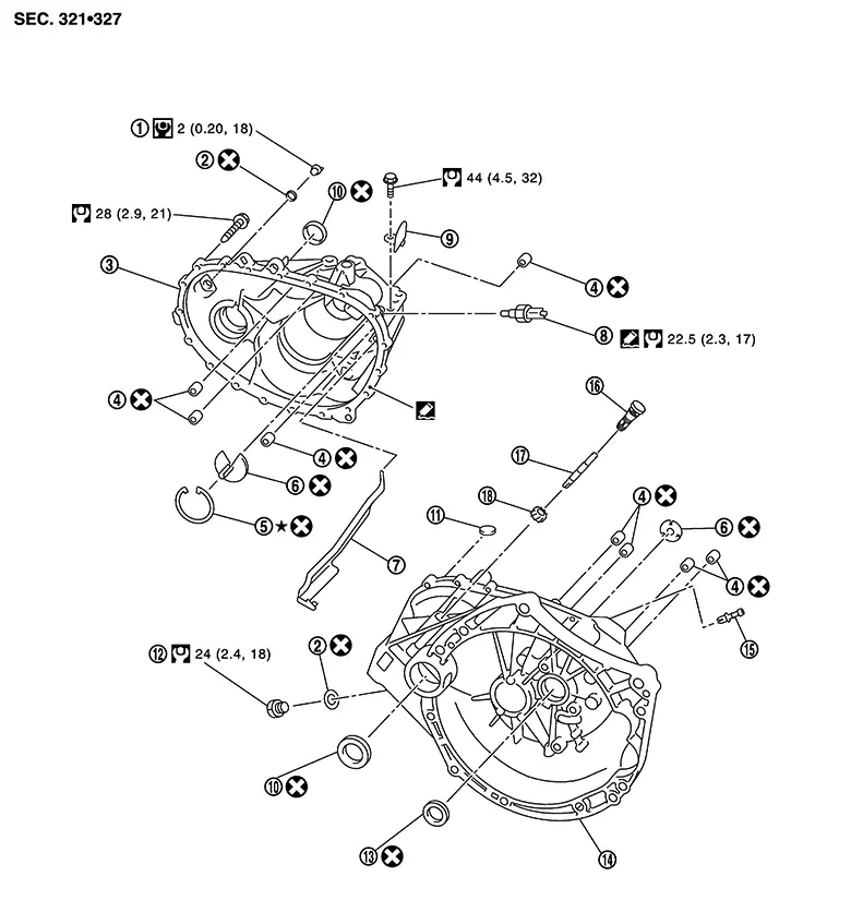
CASE AND HOUSING
|
1. |
Filler plug |
2. |
Gasket |
3. |
Transaxle case |
|
4. |
Bushing |
5. |
Snap ring |
6. |
Oil channel |
|
7. |
Oil gutter |
8. |
Position switch |
9. |
Bracket |
|
10. |
Differential side oil seal |
11. |
Magnet |
12. |
Drain plug |
|
13. |
Input shaft oil seal |
14. |
Clutch housing |
15. |
2 way connector |
|
16. |
Plug |
17. |
Pinion shaft |
18. |
Pinion gear |
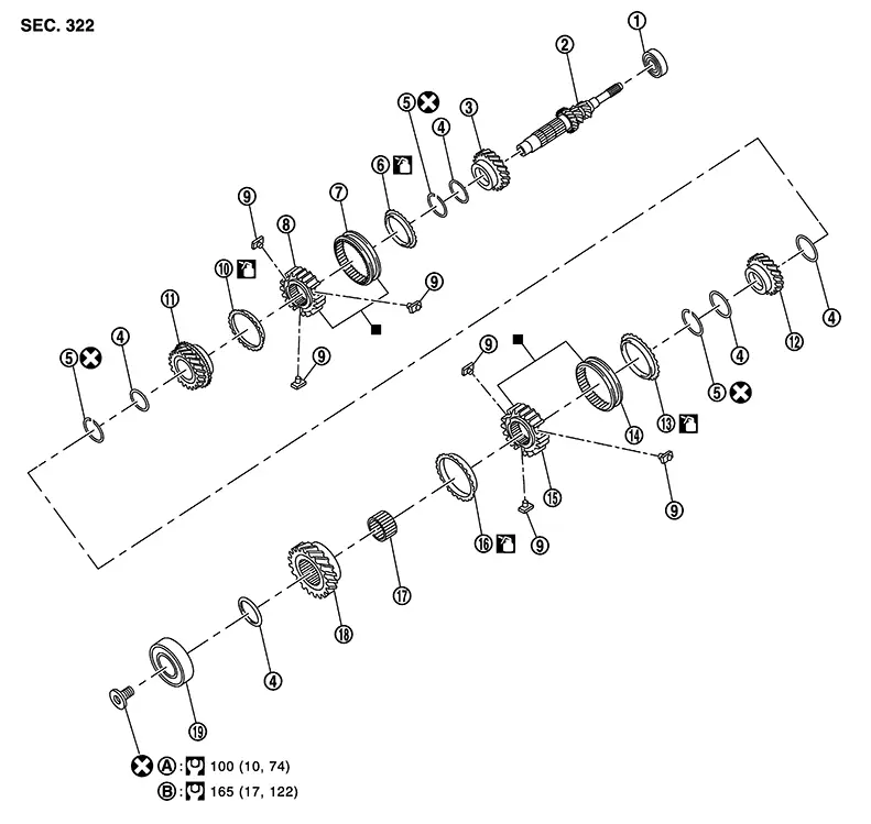
SHAFT AND GEAR
|
1. |
Input shaft front bearing |
2. |
Input shaft |
3. |
3rd input gear |
|
4. |
Spacer |
5. |
Snap ring |
6. |
3rd baulk ring |
|
7. |
3rd-4th coupling sleeve |
8. |
3rd-4th synchronizer hub |
9. |
Insert key |
|
10. |
4th baulk ring |
11. |
4th input gear |
12. |
5th input gear |
|
13. |
5th baulk ring |
14. |
5th-6th coupling sleeve |
15. |
5th-6th synchronizer hub |
|
16. |
6th baulk ring |
17. |
Needle bearing |
18. |
6th input gear |
|
19. |
Input shaft rear bearing |
A. |
First step |
B. |
Final step |
|
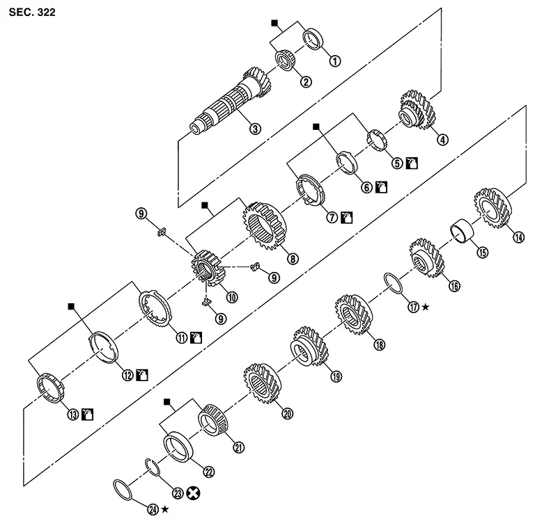
1. |
Mainshaft front bearing outer race |
2. |
Mainshaft front bearing inner race |
3. |
Mainshaft |
|
4. |
1st main gear |
5. |
1st inner baulk ring |
6. |
1st synchronizer cone |
|
7. |
1st outer baulk ring |
8. |
1st-2nd coupling sleeve |
9. |
Insert key |
|
10. |
1st-2nd synchronizer hub |
11. |
2nd outer baulk ring |
12. |
2nd synchronizer cone |
|
13. |
2nd inner baulk ring |
14. |
2nd main gear |
15. |
Bushing |
|
16. |
3rd main gear |
17. |
Mainshaft adjusting shim |
18. |
4th main gear |
|
19. |
5th main gear |
20. |
6th main gear |
21. |
Mainshaft rear bearing inner race |
|
22. |
Mainshaft rear bearing outer race |
23. |
Snap ring |
24. |
Mainshaft rear bearing adjusting shim |
|
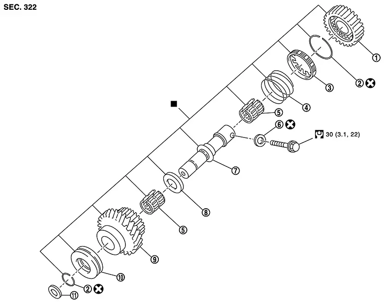
1. |
Reverse output gear |
2. |
Snap ring |
3. |
Reverse baulk ring |
|
4. |
Return spring |
5. |
Needle bearing |
6. |
Seal washer |
|
7. |
Reverse idler shaft |
8. |
Spacer |
9. |
Reverse input gear |
|
10. |
Lock washer |
11. |
Spring washer |
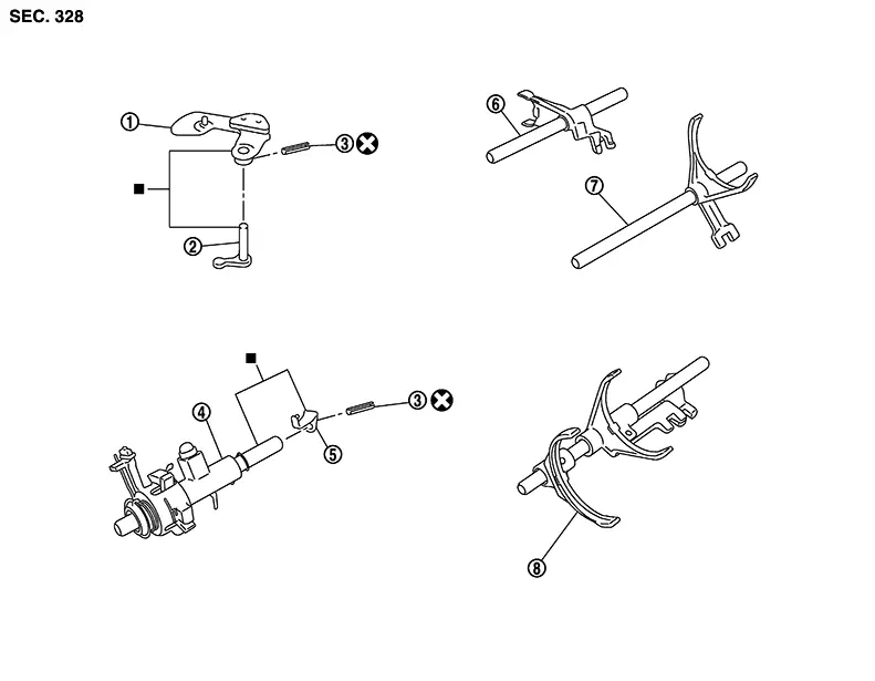
SHIFT FORK AND FORK ROD
|
1. |
Shifter lever A |
2. |
Shifter lever B |
3. |
Retaining pin |
|
4. |
Selector |
5. |
Selector lever |
6. |
Reverse fork rod |
|
7. |
1st-2nd fork rod |
8. |
Fork rod |
||
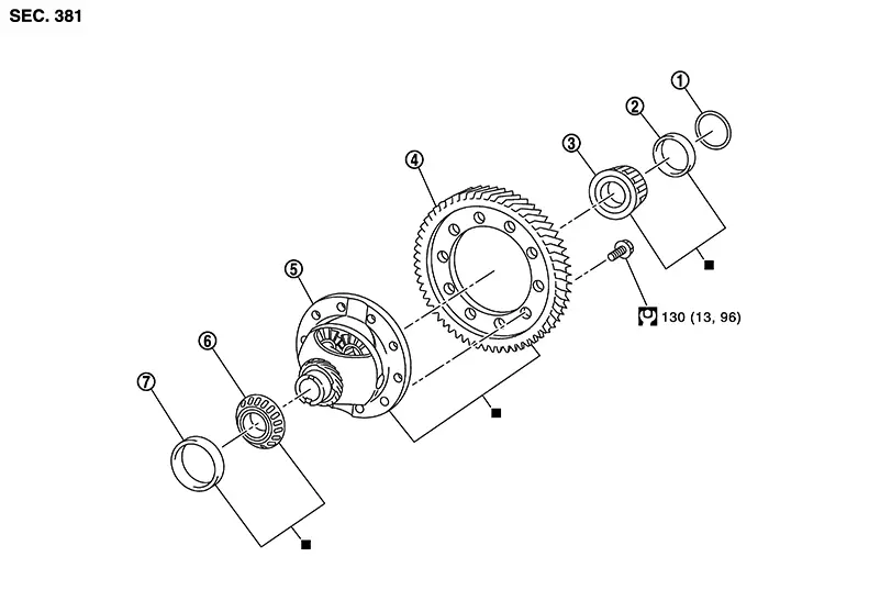
FINAL DRIVE
|
1. |
Shim |
2. |
Differential side bearing outer race (transaxle case side) |
3. |
Differential side bearing inner race (transaxle case side) |
|
4. |
Final gear |
5. |
Differential case |
6. |
Differential side bearing inner race (clutch housing side) |
|
7. |
Differential side bearing outer race (clutch housing side) |
Disassembly
Disassembly
Remove drain plug and gasket from clutch housing, using a suitable tool and drain gear oil.
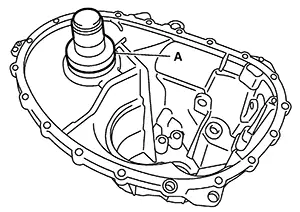
Remove filler plug and gasket from transaxle case.
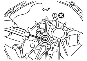
Remove
selector lever (1) retaining pin with a pin punch to remove
selector lever. 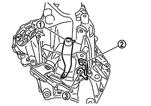
Remove bracket (2) and position switch (3) from transaxle case.
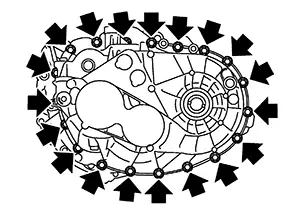
Remove
transaxle case bolts ( ).
).
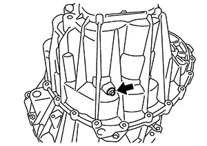
Remove
reverse idler shaft bolt ()
and sealing washer.
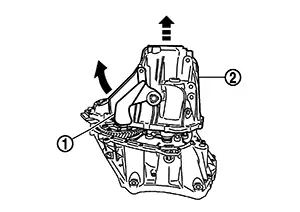
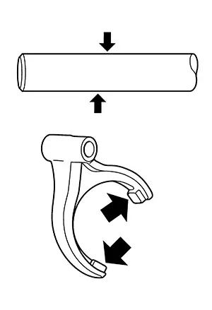
Remove
transaxle case (2) while rotating shifter lever A (1) in the
direction as shown.
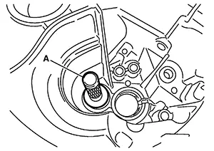
Remove
selector spring (1) from return bushing (A).
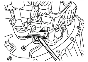
Shift
1st-2nd fork rod (1), fork rod (2), and reverse fork rod (3) to the
neutral position. 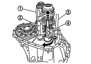
Remove selector (4) from clutch housing.
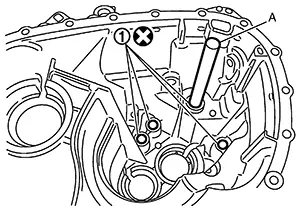
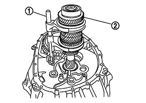
Remove
reverse idler shaft assembly (1), with the following
procedure. 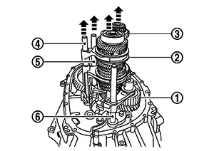 Pull
up input shaft assembly (2), mainshaft assembly (3), fork rod (4),
and 1st-2nd fork rod (5). Note:
Pull
up input shaft assembly (2), mainshaft assembly (3), fork rod (4),
and 1st-2nd fork rod (5). Note: 
It is easier to pull up when shifting each fork rod to each shaft side.
Remove reverse idler shaft assembly and reverse fork rod (6) from clutch housing.Remove spring washer from clutch housing.
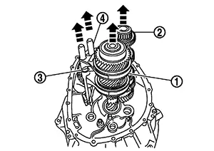
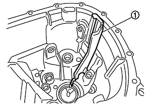
Pull up and
remove input shaft assembly (1), mainshaft assembly (2), fork rod
(3), and 1st-2nd fork rod (4) from clutch housing.
 Note:
Note:
It is easier to pull up when shifting each fork rod to each shaft side.
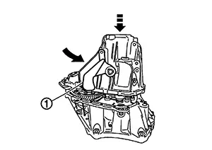
Remove
final drive assembly (1) from clutch housing. 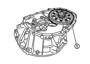
Remove magnet from clutch housing.
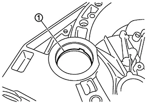
Remove
differential side oil seals (1) from clutch housing and transaxle
case.
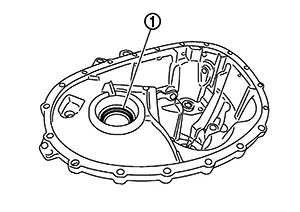
CAUTION:
Do not damage clutch housing and transaxle case.
Do not reuse differential side oil seal.
Remove
differential side bearing outer race (1) from clutch housing, using
a suitable tool.
CAUTION:
Do not damage clutch housing.
Remove
differential side bearing outer race (1) from transaxle case, using
a suitable tool. 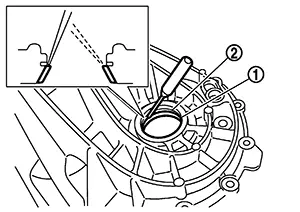
CAUTION:
Do not damage transaxle case.
Remove shim (2) from transaxle case.
Remove
shifter lever A (1) retaining pin, using a suitable tool. 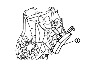
CAUTION:
Do not reuse retaining pin.
Remove shifter lever A from transaxle case.
Remove
shifter lever B (1) from transaxle case.
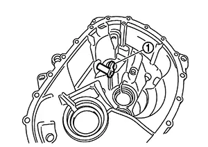
Remove oil
gutter (1) from transaxle case.
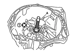
Remove
bushings (1) from transaxle case, using a suitable tool.
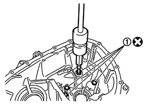
CAUTION:
Do not reuse bushings.
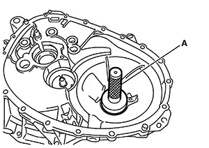
Remove
mainshaft rear bearing outer race from transaxle case, using a
suitable tool. 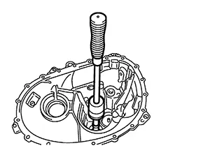
Remove mainshaft rear bearing adjusting shim from transaxle case.
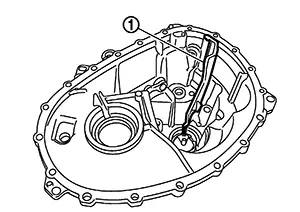
Remove snap
ring (1) and oil channel (2) from transaxle case.
CAUTION:
Do not reuse snap ring or oil channel.
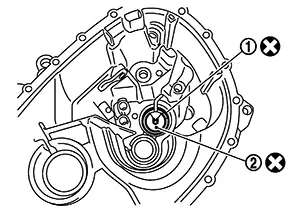
Remove
input shaft oil seal (1) from clutch housing, using a suitable
tool.
CAUTION:
Do not damage clutch housing.
Do not reuse input shaft oil seal.
Remove
mainshaft front bearing outer race (1) from clutch housing, using
Tool (A) and a suitable tool (B). 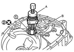
|
Tool number (A) |
: KV381054S0 (NI-34286) |
Remove oil channel (2) from clutch housing.
CAUTION:
Do not reuse oil channel.
Remove
bushings (1) from clutch housing, using a suitable tool.
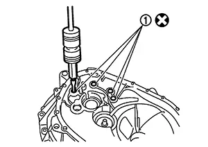
CAUTION:
Do not reuse bushings.
Remove 2
way connector (1) from clutch housing. 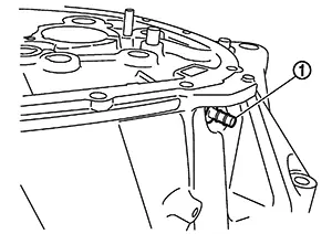
Assembly
Assembly
Install 2
way connector (1) to clutch housing.
Install
bushings (1) so that they becomes even with clutch housing surface,
using suitable tool (A). 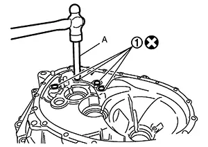
Install oil channel to clutch housing.
CAUTION:
Do not reuse oil channel.
Install
mainshaft front bearing outer race to clutch housing using Tool
(A).
CAUTION:
Replace mainshaft front bearing outer race and mainshaft front bearing inner race as a set.
Do not reuse mainshaft front bearing inner or outer race.
|
Tool number (A) |
: KV38100200 (  —  ) |
Install input shaft oil seal (1) to clutch housing using the Tool (A).
|
Tool number (A) |
: ST33220000 (  —  ) |
Install
snap ring (1) and oil channel (2) to transaxle case. 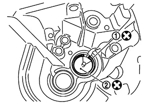
CAUTION:
-
Select and install snap ring that has the same thickness as previous one.
-
Replace transaxle assembly when replacing transaxle case.
Install mainshaft rear bearing adjusting shim to transaxle case.
CAUTION:
Select mainshaft rear bearing adjusting shim, with the following procedure when replacing mainshaft adjusting shim, 6th main gear, 5th main gear, or 4th main gear.
-
Replace mainshaft adjusting shim.
-
If new mainshaft adjusting shim is thinner than previous one, offset the thickness difference by selecting thicker mainshaft rear bearing adjusting shim.
-
If new mainshaft adjusting shim is thicker than previous one, offset the thickness difference by selecting thinner mainshaft rear bearing adjusting shim.
-
-
Replace 6th main gear, 5th main gear, or 4th main gear.
-
Measure the thickness of the main gear used before and the new main gear
-
Increase the thickness of the mainshaft rear bearing adjusting shim, if the difference is smaller than 0.025 mm (0.0010 in).
-
Decrease the thickness of the mainshaft rear bearing adjusting shim, if the difference is greater than 0.025 mm (0.0010 in).
-
Install
mainshaft rear bearing outer race to transaxle case using suitable
tool (A).
CAUTION:
Replace mainshaft rear bearing outer race and mainshaft rear bearing inner race as a set.
|
Tool number |
: KV38100200 (  —  ) |
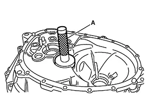
Install
bushings (1) to transaxle case, using suitable tool (A).
Install oil
gutter (1) to transaxle case.
Install
shifter lever B (1) to transaxle case.
CAUTION:
Replace shifter lever A and shifter lever B as a set.
Install shifter lever A to transaxle case.
CAUTION:
Replace shifter lever A and shifter lever B as a set.
Install
retaining pin to shifter lever A (1) using a suitable tool. 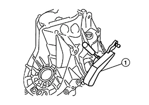
CAUTION:
Do not reuse retaining pin.
Install shim to transaxle case.
Install
differential side bearing outer race (transaxle case side) to
transaxle case, using Tool (A).
CAUTION:
Replace differential side bearing outer race (transaxle case side) and differential side bearing inner race (transaxle case side) as a set.
Do not reuse differential side bearing inner or outer race.
|
Tool number |
: ST33400001 (NI-26082) |
Install
differential side bearing outer race (clutch housing side) to
clutch housing, using Tool (A).
CAUTION:
Replace differential side bearing outer race (clutch housing side) and differential side bearing inner race (clutch housing side) as a set.
Do not reuse differential side bearing inner or outer race.
|
Tool number |
: KV38100200 (  —  ) |
Install
differential side oil seals (1) to clutch housing and transaxle
case, using Tools. 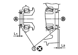
|
Tool number |
: KV32500QAA |
|
Tool number |
: B.vi 1666-B |
|
(A) |
: Transaxle case side |
|
(B) |
: Clutch housing side |
|
Dimension (L1) |
: 1.2 – 1.8 mm (0.047 – 0.071 in) |
|
Dimension (L2) |
: 2.7 – 3.3 mm (0.106 – 0.130 in) |
CAUTION:
-
Do not incline differential side oil seal.
-
Do not damage clutch housing and transaxle case.
Install magnet to clutch housing.
Install final drive assembly to clutch housing.
Set fork
rod (1) to input shaft assembly (2), and then install them to
clutch housing.
Install
mainshaft assembly (1), with the following procedure. 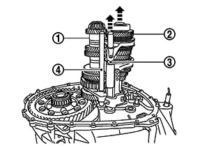 Pull
up input shaft assembly (2) and fork rod (3). Set
1st-2nd fork rod (4) to mainshaft assembly and install them to
clutch housing.
Pull
up input shaft assembly (2) and fork rod (3). Set
1st-2nd fork rod (4) to mainshaft assembly and install them to
clutch housing.
Install
reverse idler shaft assembly (1) with the following
procedure. Install spring washer to
clutch
housing. Pull
up input shaft assembly (2), mainshaft assembly (3), fork rod (4),
and 1st-2nd fork rod (5). Note:
It is easier to pull up when shifting each fork rod to each shaft side.
Set reverse fork rod (6) to reverse idler shaft assembly and install them to clutch housing. Move
1st-2nd fork rod (1), fork rod (2), and reverse fork rod (3) to the
neutral position. 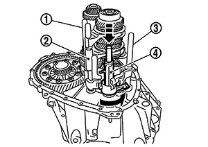
Install selector (4) to clutch housing.
CAUTION:
Replace selector lever and selector as a set.
Install
selector spring (1) to return bushing (A).
Apply recommended sealant to the gasket surface of transaxle case.
-
Use Genuine Silicone RTV or an equivalent.Refer toRecommended Chemical Products and Sealants.
CAUTION:
-
Do not allow old liquid gasket, moisture, oil, or foreign matter to remain on gasket surface.
-
Check that the gasket surface is not damaged.
-
Apply sealant bead continuously.
Install
transaxle case to clutch housing while rotating shifter lever A (1)
in the direction as shown.
Install
reverse idler shaft bolt (), as per the following procedure. Install sealing washer to reverse
idler shaft bolt, and install reverse idler shaft bolt to transaxle
case.
CAUTION:
Do not reuse sealing washer.
Tighten reverse idler shaft bolt to the specified torque.Tighten
transaxle case bolts ()
to the specified torque.
Install
position switch (1), with the following procedure. 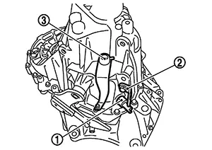 Apply
recommended sealant to threads of position switch.
Apply
recommended sealant to threads of position switch.
-
Use Genuine Silicone RTV or an equivalent.Refer to Recommended Chemical Products and Sealants .
CAUTION:
Do not allow old liquid gasket, moisture, oil, or foreign matter to remain on thread.
Install position switch to transaxle case and tighten it to the specified torque.Install bracket (2) to transaxle case and tighten bolt to the specified torque.
Install selector lever (3) with the following procedure. Install selector lever to transaxle case.
CAUTION:
Replace selector lever and selector as a set.
Install retaining pin to selector lever using a suitable tool.CAUTION:
Do not reuse retaining pin.
Install drain plug with the following procedure. Install gasket to drain plug.
CAUTION:
Do not reuse gasket.
Install drain plug to clutch housing using a suitable tool. Tighten drain plug to the specified torque.CAUTION:
Do not overtighten drain plug as this could cause the transaxle case to crack.
Install filler plug with the following procedure. Install gasket to filler plug and install it to the transaxle case.
CAUTION:
Do not reuse gasket.
Tighten filler plug to the specified torque.CAUTION:
Fill with gear oil before tighten filler plug to the specified torque.
Do not overtighten the filler plug as this could cause the transaxle case to crack.
Inspection
Inspection
INSPECTION AFTER DISASSEMBLY
Check contact surface ()
and sliding surface ()
for excessive wear, uneven wear, bend, and damage. Replace if
necessary.
Other materials:
B2fa9-11 Shift Position
Dtc Description
DTC Description
DTC DETECTION LOGIC
DTC No.
CONSULT screen items
(Trouble diagnosis
content)
DTC detecting condition
...
B2083-23 Request Sw (fr)
Dtc Description
DTC Description
DTC DETECTION LOGIC
DTC No.
CONSULT screen terms
(Trouble diagnosis
content)
DTC Detection Condition
...
C1741-21 Tire Pressure Sensor No Data Fl
Dtc Description
DTC Description
Note:
The Signal Tech II Tool [– (NI-50190)] can be used
to perform the following functions: Refer to the Signal Tech II User
Guide for additional information.
Activate and display TPMS sensor IDs
Display tire pressure rep ...