Nissan Sentra B18 (2020-2025) Service Manual: Exhaust Manifold
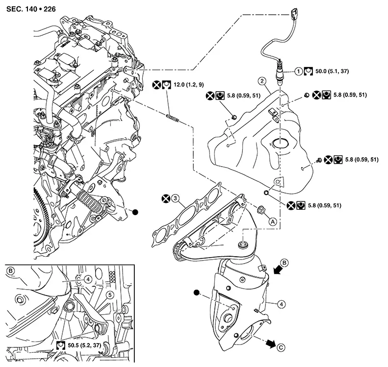
Exploded View
Exploded View
|
1. |
Air fuel ratio (A/F) sensor 1 |
2. |
Exhaust manifold cover |
3. |
Exhaust manifold gasket |
|
4. |
Exhaust manifold |
5. |
Exhaust manifold stay |
A. |
Refer to Removal and Installation. |
|
B. |
View B |
C. |
To exhaust front tube. Refer to Exploded View. |
 :
Indicates that the part is connected at points with same symbol in
actual Nissan Sentra vehicle.
:
Indicates that the part is connected at points with same symbol in
actual Nissan Sentra vehicle.
Removal and Installation
Removal and Installation
REMOVAL
Remove the front suspension member. Refer to Removal and Installation.
Remove the EGR inlet tube heat shield. Refer to Exploded View.
Remove the bolts securing the EGR inlet tube to the exhaust manifold. Refer to Exploded View.
Remove exhaust front tube. Refer to Exploded View.
Disconnect the harness connector from the air fuel ratio (A/F) sensor 1.
Disengage the air fuel ratio (A/F) sensor 1 harness from the harness retainer on the exhaust manifold cover.
Unbolt and reposition vacuum delay valve bracket. Refer to Exploded View.
Remove exhaust manifold cover.
Remove exhaust manifold stay.
Loosen
exhaust manifold nuts in reverse of the sequence shown and remove
exhaust manifold.
CAUTION:
Do not reuse exhaust manifold nuts.
Remove exhaust manifold gasket.
CAUTION:
-
Cover engine openings to avoid entry of foreign materials.
-
Do not reuse exhaust manifold gasket.
Remove the air fuel ratio (A/F) sensor 1 using Tool (if necessary).
|
Tool number |
: KV991J0050 (NI-44626) |
CAUTION:
Handle air fuel ratio sensor 1 carefully and avoid impacts.
Remove exhaust manifold stud from cylinder head (if necessary).
CAUTION:
Do not reuse exhaust manifold stud.
INSTALLATION
Install exhaust manifold stud (if necessary).
CAUTION:
Do not reuse exhaust manifold stud.
Install exhaust manifold gasket to cylinder head.
CAUTION:
Do not reuse exhaust manifold gasket.
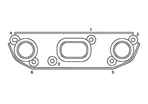
Install
exhaust manifold and tighten exhaust manifold nuts to the specified
torque in the sequence shown.
CAUTION:
Do not reuse exhaust manifold nuts.
Note:
Repeat tightening sequence to ensure exhaust manifold nuts are tightened to the specified torque.
|
Exhaust manifold nuts |
: 33.4 N·m (3.4 kg-m, 25 ft-lb) |
Installation of the remaining parts in the reverse order of removal.
CAUTION:
-
Before installing the air fuel ratio (A/F) sensor 1, clean the exhaust manifold threads using oxygen sensor thread cleaner tool and apply anti-seize lubricant or equivalent.
Oxygen sensor thread cleaner
: — (NI-43897-18)
-
Do not over-tighten the air fuel ratio (A/F) sensor 1. Doing so may cause damage, resulting in a malfunction and the MIL coming on.
Tool number
: KV991J0050 (NI-44626)
Inspection
Inspection
INSPECTION AFTER REMOVAL
Surface Distortion
-
Using suitable tool (A) and suitable tool (B), check the surface distortion of exhaust manifold mating surface in each exhaust port and entire part.
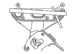
Limit
: Refer to Exhaust Manifold.
-
If it exceeds the limit, replace exhaust manifold.
INSPECTION AFTER INSTALLATION
Check the joint of parts with the engine in running state. Check that there is no leaks of exhaust gas and abnormal sound.
Other materials:
Mode Door Motor
Diagnosis Procedure
Diagnosis Procedure
CHECK MODE DOOR MOTOR POWER SUPPLY
Ignition switch ON.
Check voltage between mode door motor harness connector
and ground.
...
Primary Pressure Solenoid Valve Circuit
Diagnosis Procedure
Diagnosis Procedure
CHECK HARNESS CONNECTOR
Ignition switch OFF.
Check the mating condition of TCM
harness connector and CVT unit harness
connector.
Is the inspect ...
Maintenance precautions
When performing any inspection, servicing, or maintenance work on your Nissan
Sentra, always exercise extreme care to avoid serious personal injury or accidental
damage to the vehicle. Routine maintenance plays an important role in the long-term
reliability, safety, and performance of the Niss ...