Nissan Sentra B18 (2020-2025) Service Manual: Mode Door Motor
Diagnosis Procedure
Diagnosis Procedure
-
CHECK MODE DOOR MOTOR POWER SUPPLY
-
-
Ignition switch ON.
-
Check voltage between mode door motor harness connector and ground.
+
–
Voltage
(Approx.)
Mode door motor
Connector
Terminal
M166
1
Ground
Battery voltage
-
Is the inspection result normal?
YES >>GO TO 2.
NO >>GO TO 5.
-
-
CHECK MODE DOOR MOTOR GROUND CIRCUIT
-
-
Ignition switch OFF.
-
Disconnect mode door motor connector and A/C amp. connector.
-
Check continuity between mode door motor harness connector and ground.
Mode door motor
—
Continuity
Connector
Terminal
M166
2
Ground
Yes
-
Is the inspection result normal?
YES >>GO TO 3.
NO >>Repair harness or connector.
-
-
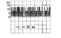
CHECK MODE DOOR MOTOR LIN SIGNAL
-
-
Connect mode door motor connector and A/C amp. connector.
-
Ignition switch ON.
-
Confirm output waveform between mode door motor harness connector and ground using oscilloscope.
+
—
Output waveform
Mode door motor
Connector
Terminal
M166
3
Ground
-
Is the inspection result normal?
YES >>GO TO 4.
NO >>GO TO 6.
-
-
CHECK INSTALLATION OF MODE DOOR MOTOR
-
Check mode door motor is properly installed. Refer to Exploded View.
Is the inspection result normal?
YES >>Replace mode door motor. Refer to Removal and Installation.
NO >>Repair or replace malfunctioning part.
-
-
CHECK MODE DOOR MOTOR POWER SUPPLY CIRCUIT FOR OPEN
-
-
Ignition switch OFF.
-
Disconnect mode door motor connector and A/C amp. connector.
-
Check continuity between mode door motor harness connector and A/C amp. connector.
Mode door motor
A/C amp.
Continuity
Connector
Terminal
Connector
Terminal
M166
1
M81
1
Yes
-
Is the inspection result normal?
YES >>Replace A/C amp. Refer to Removal and Installation.
NO >>Repair harness or connector.
-
-
CHECK MODE DOOR MOTOR LIN SIGNAL CIRCUIT FOR OPEN
-
-
Ignition switch OFF.
-
Disconnect mode door motor connector and A/C amp. connector.
-
Check continuity between mode door motor harness connector and A/C amp. harness connector.
Mode door motor
A/C amp.
Continuity
Connector
Terminal
Connector
Terminal
M166
3
M81
22
Yes
-
Is the inspection result normal?
YES >>Replace A/C amp. Refer to Removal and Installation.
NO >>Repair harness or connector.
-
Other materials:
P2808-00 Pressure Control Solenoid G
Dtc Description
DTC Description
DTC DETECTION LOGIC
DTC
CONSULT screen terms
(Trouble diagnosis
content)
DTC detection
conditi ...
Front Fender
Exploded View
Exploded View
1.
Cowl top side trim cover
2.
Front fender baffle A
3.
...
B1019 Occupant Sens
Dtc Description
DTC Description
DESCRIPTION
B1019 OCCUPANT SENS
The OCS control unit is wired to the air bag
diagnosis sensor unit. The air bag diagnosis sensor unit will
monitor the OCS for failures and interruptions in communication
between the OCS control unit and the air bag ...