Nissan Sentra B18 (2020-2025) Service Manual: Door Motor Circuit
Diagnosis Procedure
Diagnosis Procedure
Note:
If all of door motor DTCs are detected, check this circuit.
-
CHECK DOOR MOTOR POWER SUPPLY
-
-
Ignition switch ON.
-
Check voltage between intake door motor harness connector and ground.
+
–
Voltage
(Approx.)
Intake door motor
Connector
Terminal
M165
1
Ground
Battery voltage
-
Is the inspection result normal?
YES >>GO TO 2.
NO >>GO TO 7.
-
-
CHECK DOOR MOTOR GROUND CIRCUIT FOR OPEN
-
-
Ignition switch OFF.
-
Disconnect intake door motor connector.
-
Check continuity between intake door motor harness connector and ground.
Intake door motor
—
Continuity
Connector
Terminal
M165
2
Ground
Yes
-
Is the inspection result normal?
YES >>GO TO 3.
NO >>Repair harness or connector.
-
-
CHECK DOOR MOTOR LIN SIGNAL
-
-
Connect intake door motor connector.
-
Ignition switch ON.
-
Confirm output waveform between intake door motor harness connector and ground with oscilloscope.
+
–
Output waveform
Intake door motor
Connector
Terminal
M165
3
Ground
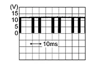
-
Is the inspection result normal?
YES >>GO TO 4.
NO >>GO TO 6.
-
-
CHECK DOOR MOTOR LIN SIGNAL CIRCUIT FOR OPEN
-
-
Ignition switch OFF.
-
Disconnect A/C amp. connector and intake door motor connector.
-
Check continuity between A/C amp. harness connector and intake door motor harness connector.
A/C amp.
Intake door motor
Continuity
Connector
Terminal
Connector
Terminal
M81
22
M165
3
Yes
-
Is the inspection result normal?
YES >>GO TO 5.
NO >>Repair harness or connector.
-
-
CHECK INTERMITTENT INCIDENT
-
Check intermittent incident. Refer to Intermittent Incident.
Inspection End.
-
-
CHECK DOOR MOTOR LIN SIGNAL CIRCUIT FOR SHORT
-
-
Ignition switch OFF.
-
Disconnect following connectors:
-
A/C amp.
-
Air mix door motor
-
Mode door motor
-
Intake door motor
-
-
Check continuity between A/C amp. harness connector and ground.
A/C amp.
—
Continuity
Connector
Terminal
M81
22
Ground
No
-
Is the inspection result normal?
YES >>Replace A/C amp. Refer to Removal and Installation.
NO >>Repair harness or connector.
-
-
CHECK DOOR MOTOR POWER SUPPLY CIRCUIT FOR OPEN
-
-
Ignition switch OFF.
-
Disconnect intake door motor connector and A/C amp. connector.
-
Check continuity between intake door motor harness connector and A/C amp. harness connector.
Intake door motor
A/C amp.
Continuity
Connector
Terminal
Connector
Terminal
M165
1
M81
1
Yes
-
Is the inspection result normal?
YES >>GO TO 8.
NO >>Repair harness or connector.
-
-
CHECK DOOR MOTOR POWER SUPPLY CIRCUIT FOR SHORT
-
-
Disconnect following connectors:
-
Air mix door motor
-
Mode door motor
-
-
Check continuity between A/C amp. harness connector and ground.
A/C amp.
—
Continuity
Connector
Terminal
M81
1
Ground
No
-
Is the inspection result normal?
YES >>Replace A/C amp. Refer to Removal and Installation.
NO >>Repair harness or connector.
-
Other materials:
Removal and Installation
Av Control Unit
Exploded View
Exploded View
1.
AV control unit bracket
(LH)
2.
AV control unit
...
Diagnosis System (intelligent Key Unit)
Consult Function (hands Free Module)
CONSULT Function
(HANDS FREE MODULE)
Intelligent Key unit
Refer to CONSULT Function
(HANDS FREE MODULE).
...
Noise, Vibration and Harshness (nvh) Troubleshooting. Nvh Troubleshooting Chart
Nvh Troubleshooting Chart
NVH Troubleshooting Chart
Use the chart below to find the cause of the
symptom. If necessary, repair or replace these parts.
...