Nissan Sentra B18 (2020-2025) Service Manual: Intake Manifold
Exploded View
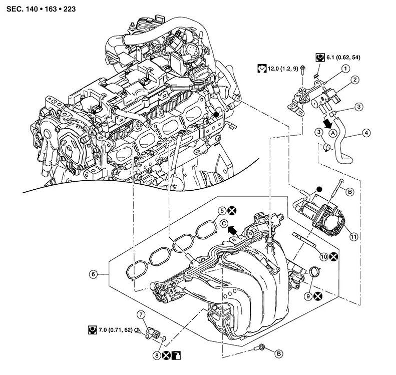
Exploded View
|
1. |
EVAP canister purge volume control solenoid valve bracket |
2. |
EVAP canister purge volume control solenoid valve |
3. |
Clamp |
|
4. |
EVAP hose |
5. |
Intake manifold gasket |
6. |
Intake manifold assembly |
|
7. |
Manifold absolute pressure (MAP) sensor |
8. |
O-ring |
9. |
EGR outlet tube gasket |
|
10. |
Electronic throttle control actuator gasket |
11. |
Electronic throttle control actuator |
A. |
To EVAP hose. Refer to Exploded View. |
|
B. |
Refer to Removal and Installation. |
C. |
To vacuum hose A. Refer to Exploded View. |
Removal and Installation
Removal and Installation
Note:
When removing components such as hoses, tubes/lines, etc., cap or plug openings to prevent fluid from spilling.
REMOVAL
Remove the air duct and resonator assembly. Refer to Exploded View.
Disconnect the harness connector from the electric throttle control actuator.
Remove electric throttle control actuator bolts and reposition.
CAUTION:
-
Handle carefully to avoid any shock to electric throttle control actuator.
-
Do not disassemble electric throttle control actuator.
-
Do not reuse electric throttle control actuator gasket.
Remove
harness retainer (A) from intake manifold. 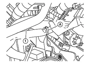
|
(1) |
: EGR outlet tube |
Disconnect
the harness connector (B) from the EVAP canister purge volume
control solenoid valve (1). 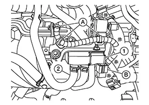
CAUTION:
Handle carefully to avoid any shock to EVAP canister purge volume control solenoid valve.
Remove the harness retainers (A) from the intake manifold and EVAP canister purge volume control solenoid valve bracket.
Remove the EVAP hose (2) from the EVAP canister purge volume control solenoid valve.
Remove the PCV hose from the intake manifold. Refer to Exploded View.
Remove the EGR volume control valve. Refer to Removal and Installation.
Remove bolts securing radiator hose bracket to intake manifold and reposition radiator hose (upper). Refer to Removal and Installation.
Remove vacuum hose from intake manifold.
Disconnect the harness connector from the manifold absolute pressure (MAP) sensor.
Remove the oil level gauge.
Remove
harness retainer (A) from intake manifold. 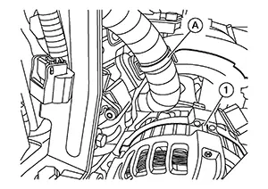
|
(1) |
: Generator |
Remove
harness connector (A) from intake manifold (1). 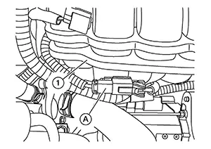
Remove engine harness from vacuum tube and reposition engine harness.
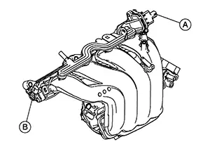
Remove
intake manifold with the following procedure: Disconnect the harness connector
from the intake manifold runner control valve motor (A) and intake
manifold runner control valve position sensor (B).
CAUTION:
-
Handle carefully to avoid any shock to intake manifold runner control valve or intake manifold runner control valve position sensor.
-
Do not remove intake manifold runner control valve motor or intake manifold runner control valve position sensor.
CAUTION:
-
Cover engine openings to avoid entry of foreign materials.
-
Do not reuse intake manifold gasket.
Disregard No. 6 when loosening.
Remove bolt and remove manifold absolute pressure (MAP) sensor (if necessary).
CAUTION:
Do not reuse O-ring.
Remove the EVAP canister purge volume control solenoid valve using the following procedure (if necessary): Remove EVAP hose from intake manifold. Remove bolts and remove EVAP canister purge volume control solenoid valve, EVAP canister purge volume control solenoid valve bracket and EVAP hose from intake manifold.
INSTALLATION
Install the intake manifold gasket into the groove of intake manifold.
CAUTION:
Do not reuse intake manifold gasket.
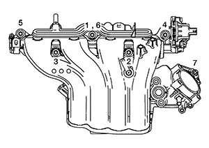
Install the
intake manifold using the following procedure: Hand
tighten bolts 4 and 5 as shown. Tighten
the intake manifold bolts to
the specified torque in the sequence shown.
|
Intake manifold bolts |
: 25.0 N·m (2.6 kg-m, 18 ft-lb) |
Installation of the remaining components is in the reverse order of removal.
Electric Throttle Control Actuator
-
Tighten electric throttle control actuator bolts to the specified torque diagonally over several steps.
CAUTION:
Do not reuse electric throttle control actuator gasket.
Electric throttle control actuator bolts
: 10.0 N·m (1.0 kg-m, 89 in-lb)
-
Perform “Throttle Valve Closed Position Learning” after repair when removing harness connector of the electric throttle control actuator. Refer to Work Procedure.
Other materials:
Heater & Air Conditioning System. Removal and Installation
Compressor
Exploded View
Exploded View
1.
Compressor
Front
Removal and Installation
Removal and Installation
REM ...
Normal Operating Condition
Symptom Description
Symptom Description
FUEL CUT CONTROL (AT NO LOAD AND HIGH ENGINE SPEED)
If the status of that the engine speed is above 2,500 rpm under no
load (at 0 km/h and the selector lever position is P or N) takes more than the
specified time, fuel will be cut off after s ...
P0315 Ckp Sensor (pos)
Dtc Description
DTC Description
DTC DETECTION LOGIC
DTC
CONSULT screen terms
(Trouble diagnosis
content)
DTC detection
condition
...