Nissan Sentra B18 (2020-2025) Service Manual: Heater & Air Conditioning System :: Removal and Installation
Compressor. Exploded View
Exploded View
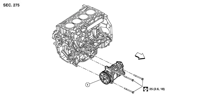
|
1. |
Compressor |
|
Front |

Removal and Installation
Removal and Installation
REMOVAL
Discharge the refrigerant. Refer to Recycle Refrigerant.
Partially remove the front fender protector (RH). Refer to Exploded View.
Remove the front under cover. Refer to Removal and Installation.
Remove the
drive belt from the compressor. Refer to Removal and Installation. Note: 
Complete removal of the drive belt is not necessary.
Remove bolt (A) from high-pressure flexible hose (1) and disconnect high-pressure flexible hose (1) from the compressor (2).
CAUTION:
Cap or wrap the joint of the A/C pipes with suitable material such as vinyl tape to avoid the entry of air.
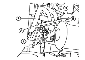
Remove nut (B) from internal heat exchanger (3) and disconnect internal heat exchanger (3) from the compressor (2).
CAUTION:
Cap or wrap the joint of the A/C pipes with suitable material such as vinyl tape to avoid the entry of air.
Disconnect the harness connectors from the compressor.
Remove the compressor bolts and the compressor.
INSTALLATION
Installation is in the reverse order of removal.
CAUTION:
-
Do not reuse the O-rings.
-
Apply A/C compressor oil to the new O-rings for installation.
-
After charging the A/C refrigerant, check for leaks. Refer to Leak Test.
Magnet Clutch
Removal and Installation
Removal and Installation
REMOVAL
Remove front wheel and tire (RH). Refer to Removal and Installation.
Partially remove the front fender protector (RH). Refer to Exploded View.
Remove the front under cover. Refer to Removal and Installation.
Remove the
drive belt from the compressor. Refer to Removal and Installation. Note:
Complete removal of the drive belt is not necessary.
Hold clutch
disc (1) using tool (A) then remove center bolt (B). 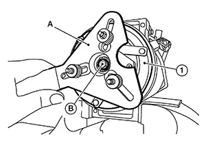
Remove the clutch disc and shim(s).
CAUTION:
Retain shim(s) for installation.
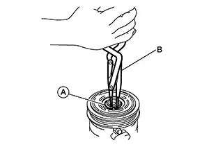
Remove the
snap ring (A) using a suitable tool (B).
Remove the
pulley assembly using suitable tool (A).
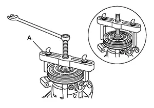
CAUTION:
To prevent deformation of the pulley groove, the puller claws should be hooked under (not into) the pulley groove.
Remove the
magnet coil snap ring (A) using a suitable tool.
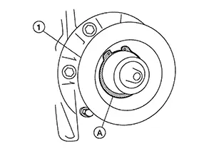
Then remove the magnet coil (1) from compressor shaft.
INSPECTION AFTER REMOVAL
Clutch Disc
If the contact surface shows signs of damage due to excessive heat, replace clutch disc and pulley.
Pulley
Check the appearance of the pulley assembly. If the contact surface of the pulley shows signs of excessive grooving, replace the clutch disc and pulley. The contact surfaces of the pulley assembly should be cleaned with a suitable solvent before installation.
Magnet Coil
Check the magnet coil for a loose connection or cracked insulation.
INSTALLATION
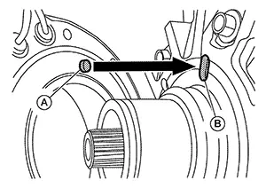
Install the magnet coil.
CAUTION:
Be sure to align the magnet coil pin (A) with the hole (B) in the compressor front head.
Install the
magnet coil (1) on the compressor shaft with the snap ring (A)
using suitable tool.
Install the
pulley assembly (1) using Tool (A).
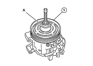
|
Tool number |
: — (NI-38873-A) |
Install the
snap ring (A) using a suitable tool (B).
Hold clutch
disc using tool (A) then tighten center bolt.
Installation of remaining components is in reverse order of removal.
INSPECTION OF CLUTCH DISC TO PULLEY CLEARANCE
Check the
clearance (A) all the way around between the clutch disc (1) and
pulley (2).
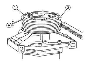
|
Clutch disc to pulley clearance |
: 0.35 - 0.65 mm (0.014 - 0.026 in) |
If specified clearance is not obtained, replace compressor clutch.
BREAK-IN OPERATION
When replacing compressor clutch assembly, always conduct the break-in operation. This is done by engaging and disengaging the clutch about 30 times. Break-in operation raises the level of transmitted torque.
Cooler Pipe and Hose. Exploded View
Exploded View
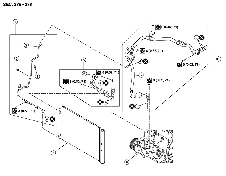
|
1. |
High-pressure pipe assembly |
2. |
High-pressure pipe |
3. |
Clip |
|
4. |
O-ring |
5. |
High-pressure flexible hose assembly |
6. |
High-pressure flexible hose |
|
7. |
Condenser |
8. |
Compressor |
9. |
Internal heat exchanger |
|
10. |
Internal heat exchanger assembly |
High-Pressure Flexible Hose
Removal and Installation
Removal and Installation
REMOVAL
Discharge the refrigerant. Refer to Recycle Refrigerant.
Remove front under cover. Refer to Removal and Installation.
Remove nut
(A) and disconnect the high-pressure flexible hose (1) from
compressor (2). 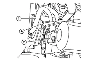
Remove core support cover. Refer to Exploded View.
Remove bolt
(A) and disconnect the high-pressure flexible hose from the
condenser.
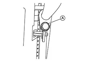
CAUTION:
Cap or wrap the joint of the hose with suitable material such as vinyl tape to avoid the entry of air.
Remove the high-pressure flexible hose.
INSTALLATION
Installation is in the reverse order of removal.
CAUTION:
-
Do not reuse O-rings.
-
Apply A/C oil to new O-rings.
-
After charging refrigerant, check for leaks. Refer to Leak Test.
High-Pressure Pipe
Removal and Installation
Removal and Installation
REMOVAL
Discharge the refrigerant. Refer to Recycle Refrigerant.
Remove bolt
(A) and disconnect high-pressure pipe from internal heat
exchanger. 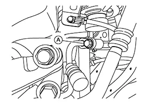
Remove core support cover. Refer to Exploded View.
Disconnect refrigerant pressure sensor and release clips from high-pressure pipe. Refer to Exploded View.
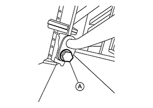
Remove bolt
(A) and disconnect the high-pressure pipe from the
condenser.
CAUTION:
Cap or wrap the joint of the pipe with a suitable material such as vinyl tap to avoid the entry of air.
Remove the high-pressure pipe.
INSTALLATION
Installation is in the reverse order of removal.
CAUTION:
-
Do not reuse O-rings.
-
Apply A/C oil to new O-rings.
-
After charging refrigerant, check for leaks. Refer to Leak Test.
Internal Heat Exchanger
Removal and Installation
Removal and Installation
REMOVAL
Discharge the refrigerant. Refer to Recycle Refrigerant.
Remove front under cover. Refer to Removal and Installation.
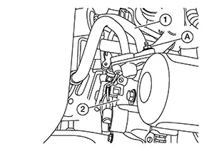
Remove nut
(A) and disconnect internal heat exchanger (1) from compressor
(2). 
Remove bolt
(A) and disconnect internal heat exchanger from expansion
valve. 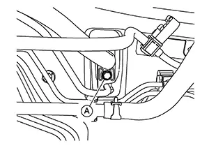
Remove bolt
(A) and disconnect high-pressure pipe from internal heat
exchanger.
Remove nut
(A) and separate internal heat exchanger from body. 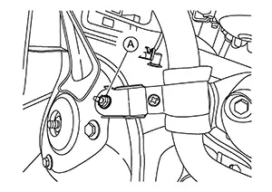
Remove internal heat exchanger.
INSTALLATION
Installation is in the reverse order of removal.
CAUTION:
-
Do not reuse O-rings.
-
Apply A/C oil to new O-rings.
-
After charging refrigerant, check for leaks. Refer to Leak Test.
Refrigerant Pressure Sensor
Removal and Installation
Removal and Installation
The refrigerant pressure sensor is an integral part of the high pressure pipe.
If replacement of the refrigerant pressure sensor is necessary, replace the high pressure pipe. Refer to Removal and Installation.
Condenser. Exploded View
Exploded View
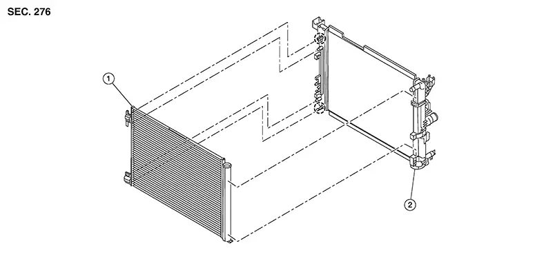
|
1. |
Condenser |
2. |
Radiator |
|
Pawl |

Removal and Installation
Removal and Installation
REMOVAL
Discharge the refrigerant. Refer to Recycle Refrigerant.
Remove the front bumper. Refer to Removal and Installation.
Remove air guides. Refer to Exploded View.
Remove bolt (A) and disconnect high-pressure flexible hose from condenser.
CAUTION:
Cap or wrap the joint of the hose with suitable material such as vinyl tape to avoid the entry of air.
Remove bolt (A) and disconnect high-pressure pipe from condenser.
CAUTION:
Cap or wrap the joint of the hose with suitable material such as vinyl tape to avoid the entry of air.
Remove condenser. Refer to Exploded View.
INSTALLATION
Installation is in the reverse order of removal.
CAUTION:
-
Do not reuse O-rings.
-
Apply A/C oil to the O-rings of the condenser for installation.
-
After charging refrigerant, check for leaks. Refer to Leak Test.
Heating and Cooling Unit Assembly. Exploded View
Exploded View
Removal and Installation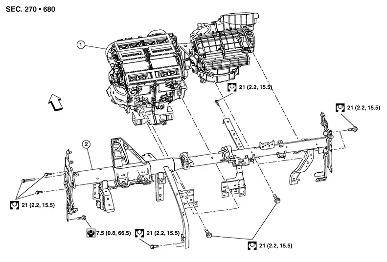
|
1. |
Heating and cooling unit assembly |
2. |
Steering member assembly |
|
Front |
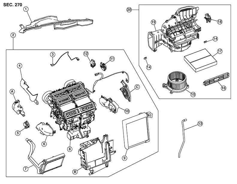
|
1. |
Air intake cover |
2. |
Heating and cooling unit assembly |
3. |
Intake sensor |
|
4. |
Heater core pipe cover |
5. |
Air mix door motor [LH (automatic A/C only)] |
6. |
Foot duct (LH) |
|
7. |
Heater core |
8. |
Heating and cooling unit |
9. |
Evaporator |
|
10. |
Front floor duct (RH) |
11. |
Mode door motor |
12. |
Air mix door motor (RH) |
|
13. |
Drain hose |
14. |
J nut |
15. |
Blower motor |
|
16. |
In-cabin microfilter cover |
17. |
In-cabin microfilter |
18. |
Intake door motor |
|
19. |
Blower unit |
20. |
Blower unit assembly |
A. |
Heater core pipe support |
|
B. |
Evaporator lower cover |
C. |
Mode door motor bracket |
Heating and Cooling Unit Assembly
Removal and Installation
Removal and Installation
REMOVAL
Discharge the refrigerant. Refer to Recycle Refrigerant.
Remove bolt
(A) and disconnect internal heat exchanger from expansion
valve.
CAUTION:
Cap or wrap the joint of the pipe with suitable material such as vinyl tape to avoid the entry of air.
Disconnect the heater hoses from the heater core.
Remove the front wiper drive assembly. Refer to Removal and Installation.
Remove
steering member bolt (A) in engine room. 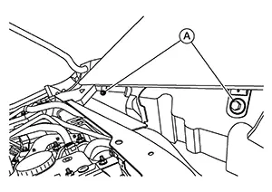
Remove the instrument panel assembly. Refer to Removal and Installation.
Remove left knee air bag module. Refer to Removal and Installation.
Remove right knee air bag module. Refer to Removal and Installation.
Remove bolt
(A) and separate lower joint (2) from steering column (1). 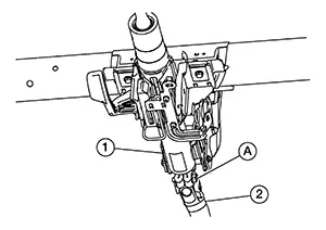
CAUTION:
Place a matching mark on both lower joint and steering column before separating lower joint.
Remove
bolts (A) and lower steering column to the floor. 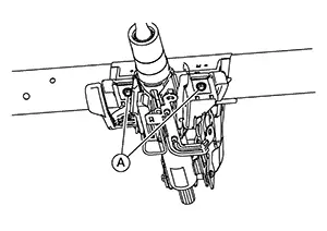
Remove heating and cooling unit assembly bolts. Refer to Exploded View.
Disconnect all necessary harness connectors.
Remove steering member bolts. Refer to Exploded View.
Lower steering member assembly to the floor and remove heating and cooling unit assembly.
INSTALLATION
Installation is in the reverse order of removal.
Blower Unit
Removal and Installation
Removal and Installation
REMOVAL
Remove the heating and cooling unit assembly. Refer to Removal and Installation.
Disconnect harness connector from intake door motor and release harness retainers.
Remove bolt
(A) and separate blower unit from the heating and cooling unit
assembly. 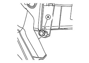
INSTALLATION
Installation is in the reverse order of removal.
Air Intake Cover
Removal and Installation
Removal and Installation
REMOVAL
Remove windshield glass. Refer to Removal and Installation.
Remove
fasteners (A) and remove air intake cover. 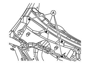
INSTALLATION
Installation is in the reverse order of removal.
Heater Core
Removal and Installation
Removal and Installation
REMOVAL
Remove the heating and cooling unit assembly. Refer to Removal and Installation.
Remove
screws (A). 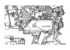
|
|
: Pawl |
Using a suitable tool, release pawl and remove foot duct LH.
Remove
screws (A) and remove heater core pipe cover (1). 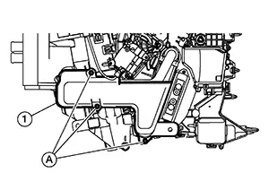
Remove
grommet (A) from heating and cooling unit assembly. 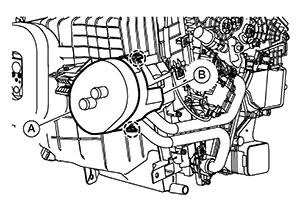
|
|
: Pawl |
Using a suitable tool, release pawls and remove heater core pipe support (B).
Remove heater core.
INSTALLATION
Installation is in the reverse order of removal.
Evaporator
Removal and Installation
Removal and Installation
REMOVAL
Remove the blower unit. Refer to Removal and Installation.
Remove heater core. Refer to Removal and Installation.
Remove
screws (A). 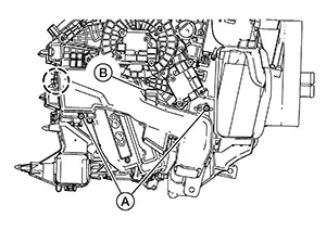
|
|
: Pawl |
Using a suitable tool, release pawl and remove foot duct RH.
Remove air mix door motor RH. Refer to Removal and Installation — Air Mix Door Motor RH (Automatic Air Conditioner) or Removal and Installation (Manual Air Conditioner).
Disconnect intake sensor.
Disconnect air mix door motor LH (if equipped). Refer to Exploded View.
Remove
screws (A) from evaporator lower cover. 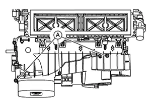
Remove
screws (A) from evaporator lower cover. 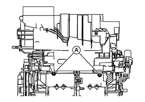
Using a
suitable tool, release pawls from evaporator lower cover. 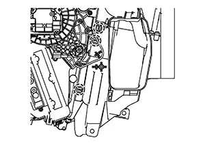
|
|
: Pawl |
Using a
suitable tool, release pawls and remove evaporator lower
cover. 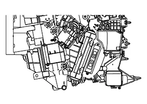
|
|
: Pawl |
Remove evaporator.
INSTALLATION
Installation is in the reverse order of removal.
Expansion Valve
Removal and Installation
Removal and Installation
The expansion valve is an integral part of the evaporator.
If replacement of the expansion valve is necessary, replace the evaporator. Refer to Removal and installation.
Other materials:
Component Parts
Exterior Lighting System
Component Parts Location
Component Parts
Location
A.
View of instrument panel
B.
M/T transmi ...
U0101 Can Comm Circuit
Dtc Description
DTC Description
CAN (Controller Area Network) is a serial communication line for
real time application. It is an on-Nissan Sentra vehicle multiplex communication line with
high data communication speed and excellent error detection ability. Many
electronic control un ...
Basic Inspection. Diagnosis and Repair Work Flow
Diagnosis and Repair Work Flow
Work Flow
Work Flow
OVERALL SEQUENCE
DETAILED FLOW
GET INFORMATION FOR SYMPTOM
Get the detailed information from the customer
about the symptom (the condition and the environment when
the incident/malfunction occurred) usi ...