Nissan Sentra B18 (2020-2025) Service Manual: Ecu Diagnosis Information
A/c Auto Amp.
Values on the Diagnosis Tool
Values on the Diagnosis Tool
Note:
The following table includes information (items) inapplicable to this Nissan Sentra vehicle: For information (items) applicable to this vehicle, refer to CONSULT display items.
|
Monitor item |
Condition |
Value/Status |
|
|---|---|---|---|
|
AMB TEMP SEN |
Ignition switch ON |
Equivalent to ambient temperature (Display range: -40 - 215° C) |
|
|
IN-VEH TEMP |
Ignition switch ON |
Equivalent to in-Nissan Sentra vehicle temperature (Display range: -40 - 215° C) When a DTC is detected, 215°C is displayed for the value for the below Data Monitor item regardless of the cause of the malfunction. |
|
|
INT TEMP SEN |
Ignition switch ON |
Equivalent to evaporator fin temperature (Display range: -40 - 215° C) When a DTC is detected, 215°C is displayed for the value for the below Data Monitor item regardless of the cause of the malfunction. |
|
|
SUNLOAD SEN |
Ignition switch ON |
Equivalent to sunload amount (Display range: 0 - 1275 W/m^2) |
|
|
AMB SEN CAL |
Ignition switch ON |
Equivalent to ambient temperature (Display range: -40 - 215° C) |
|
|
IN -VEH CAL |
Ignition switch ON |
Equivalent to in-Nissan Sentra vehicle temperature (Display range: -40 - 215° C) When a DTC is detected, 215°C is displayed for the value for the below Data Monitor item regardless of the cause of the malfunction. |
|
|
INT TEMP CAL |
Ignition switch ON |
Equivalent to evaporator fin temperature (Display range: -40 - 215° C) When a DTC is detected, 215°C is displayed for the value for the below Data Monitor item regardless of the cause of the malfunction. |
|
|
SUNL SEN CAL |
Ignition switch ON |
Equivalent to sunload amount (Display range: 0 - 1275 W/m^2) |
|
|
XM |
Ignition switch ON |
Value according to target air flow temperature (driver side) (Display range: -100 - 150) |
|
|
FAN REQ SIG |
Ignition switch ON |
Blower motor: ON |
On |
|
Blower motor: OFF |
Off |
||
|
FAN DUTY |
Engine: Run at idle after warming up |
Blower motor: ON |
25 – 81% (Display range: 0 - 100%) |
|
Blower motor: OFF |
0 |
||
|
COMP REQ SIG |
Ignition switch ON |
A/C switch : ON |
request |
|
A/C switch : OFF |
not request |
||
|
A/C comp clutch status |
Engine: Run at idle after warming up |
A/C switch : ON |
On |
|
A/C switch : OFF |
Off |
||
|
Cooling fan request |
Ignition switch ON |
Equivalent to cooling fan operation request |
|
|
Rear window defogger request |
Ignition switch ON |
Rear window defogger switch: ON |
On |
|
Rear window defogger switch: OFF |
Off |
||
|
Eco mode request |
Ignition switch ON |
Drive mode: ECO |
Request |
|
Other than above |
Not REQ |
||
|
Illumination control duty |
Ignition switch ON |
Equivalent to illumination control duty |
|
|
Refrigerant PRESS SEN value |
Ignition switch ON |
Equivalent to refrigerant pressure |
|
|
Heated steering wheel request |
Note:
This item displayed, but cannot be monitored. |
||
|
Nissan Sentra Vehicle speed |
When driving the Nissan Sentra vehicle |
Equivalent to speedometer reading (Display range: 0 - 120 km/h) |
|
|
ODO/TRIP METER |
Ignition switch ON |
Equivalent to odometer reading |
|
|
Engine RPM |
Engine: Running |
Equivalent to tachometer reading (Display range: 0 - 8191.75 rpm) |
|
|
ENG COOL TEMP |
Ignition switch ON |
Equivalent to engine coolant temperature (Display range: -40 - 215° C) |
|
Reference Value
Reference Value
TERMINAL LAYOUT
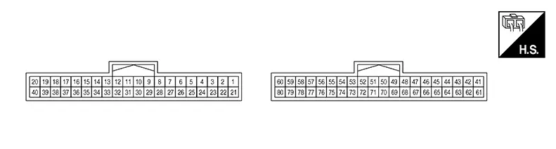
PHYSICAL VALUES
|
Terminal No. (Wire color) |
Description |
Condition |
Value (Approx.) |
||||
|---|---|---|---|---|---|---|---|
|
+ |
− |
Signal name |
Input/Output |
||||
|
1 (W) |
58 (LA/B) |
Door motor power supply |
Output |
Ignition switch ON |
Battery voltage |
||
|
22 (G) |
58 (LA/B) |
LIN1 (door motor) |
Input/Output |
Ignition switch ON |
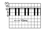 |
||
|
23 (L) |
26 (LA/BR) |
Intake sensor signal |
Input |
Ignition switch ON |
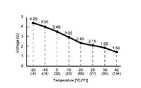 |
||
|
26 (LA/BR) |
Ground |
Sensor ground 1 |
— |
Ignition switch ON |
0 – 0.1 V |
||
|
34 (R) |
58 (LA/B) |
Blower motor control circuit |
Output |
Ignition switch ON |
Blower motor: OFF |
Battery voltage |
|
|
Blower motor: 1st speed (manual) |
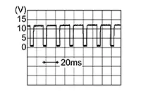 |
||||||
|
47 (G) |
78 (BR) |
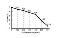
Sunload sensor signal |
Input |
Ignition switch ON |
 |
||
|
48 (Y) |
78 (BR) |
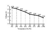
In-Nissan Sentra vehicle sensor signal |
Input |
Ignition switch ON |
 |
||
|
50 (LA/L) |
— |
CAN-High |
Input/Output |
— |
— |
||
|
552 (W) |
Ground |
Heated seat LH high relay control signal |
Output |
Heated seat ON |
0 V |
||
|
Heated seat OFF |
Battery voltage |
||||||
|
561 (V) |
Ground |
Heated steering wheel relay control signal |
Output |
Ignition switch ON |
Heated steering wheel switch: While pressing |
0 V |
|
|
Other than the above |
Battery voltage |
||||||
|
58 (LA/B) |
Ground |
Ground |
— |
Ignition switch ON |
0 – 0.1 V |
||
|
60 (P) |
58 (LA/B) |
Accessory power supply |
Input |
Ignition switch OFF (auto ACC status) or ON |
Battery voltage |
||
|
Ignition switch OFF (not auto ACC status) |
0 – 0.1 V |
||||||
|
68 (LA/SB) |
58 (LA/B) |
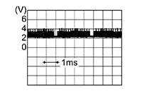
LIN2 (A/C control) |
Input/Output |
Ignition switch ON |
 |
||
|
70 (LA/P) |
— |
CAN-Low |
Input/Output |
— |
— |
||
|
752 (R) |
Ground |
Heated seat LH low relay control signal |
Output |
Heated seat ON |
0 V |
||
|
Heated seat OFF |
Battery voltage |
||||||
|
762 (LG) |
Ground |
Heated seat RH low relay control signal |
Output |
Heated seat ON |
0 V |
||
|
Heated seat OFF |
Battery voltage |
||||||
|
78 (BR) |
Ground |
Sensor ground 2 |
— |
Ignition switch ON |
0 – 0.1 V |
||
|
792 (GR) |
Ground |
Heated seat RH high relay control signal |
Output |
Heated seat ON |
0 V |
||
|
Heated seat OFF |
Battery voltage |
||||||
1: With heated steering wheel
2: With heated seat system
Fail-Safe
Fail-safe
FAIL-SAFE FUNCTION
If a communication error exists between the A/C auto amp., and the A/C switch assembly for 30 seconds or longer, air conditioning is controlled under the following conditions:
|
A/C switch |
: ON |
|
Air outlet |
: AUTO |
|
Air inlet |
: FRE (Fresh air intake) |
|
Blower fan speed |
: AUTO |
|
Set temperature |
: Setting before communication error occurs |
Dtc Inspection Priority Chart
DTC Inspection Priority Chart
If some DTCs are displayed at the same time, perform inspections one by one based on the following priority chart:
|
Priority |
Detected items (DTC) |
|---|---|
|
1 |
|
|
2 |
|
Dtc Index
DTC Index
|
DTC |
Items (CONSULT screen terms) |
Reference |
|---|---|---|
|
B24A4–11 |
INTAKE SENSOR |
DTC Diagnosis Procedure |
|
B24A4–15 |
INTAKE SENSOR |
DTC Diagnosis Procedure |
|
B24A6–11 |
IN-Nissan Sentra Vehicle SENSOR |
DTC Diagnosis Procedure |
|
B24A6–15 |
IN-Nissan Sentra Vehicle SENSOR |
DTC Diagnosis Procedure |
|
B24AF-12 |
Front heated seat relay LH (LO)* |
DTC Diagnosis Procedure |
|
B24AF-14 |
Front heated seat relay LH (LO)* |
DTC Diagnosis Procedure |
|
B24B4-02 |
A/C CONTROL |
DTC Diagnosis Procedure |
|
B24B0-12 |
Front heated seat relay LH (HI)* |
DTC Diagnosis Procedure |
|
B24B0-14 |
Front heated seat relay LH (HI)* |
DTC Diagnosis Procedure |
|
B24BA-12 |
Front heated seat relay RH (LO)* |
DTC Diagnosis Procedure |
|
B24BA-14 |
Front heated seat relay RH (LO)* |
DTC Diagnosis Procedure |
|
B24BC-12 |
Front heated seat relay RH (HI)* |
DTC Diagnosis Procedure |
|
B24BC-14 |
Front heated seat relay RH (HI)* |
DTC Diagnosis Procedure |
|
B24D4-08 |
A/C CONTROL COMM |
DTC Diagnosis Procedure |
|
B24F4-12 |
STEERING HEATER RELAY* |
DTC Diagnosis Procedure |
|
B24F4-14 |
STEERING HEATER RELAY* |
DTC Diagnosis Procedure |
|
B24F5-93 |
Mode door motor |
DTC Diagnosis Procedure |
|
B24F6-93 |
Intake door motor |
DTC Diagnosis Procedure |
|
B24F7-93 |
Air mix door motor 1 |
DTC Diagnosis Procedure |
|
B24F8-93 |
Air mix door motor 2 |
DTC Diagnosis Procedure |
|
U1010–49 |
CONTROL UNIT(CAN) |
DTC Diagnosis Procedure |
|
U2140-87 |
CAN comm err (ECM) |
DTC Diagnosis Procedure |
|
U2148-87 |
CAN comm err (brake control unit) |
DTC Diagnosis Procedure |
|
U214E-87 |
CAN comm err (combination meter) |
DTC Diagnosis Procedure |
|
U214F-87 |
CAN comm err (BCM) |
DTC Diagnosis Procedure |
|
U215B-87 |
CAN comm err (IPDM E/R) |
DTC Diagnosis Procedure |
*: if so equipped
Ecm, Bcm, Ipdm E/r
List of Ecu Reference
List of ECU Reference
|
ECU |
Reference |
|---|---|
|
ECM |
Values On The Diagnosis Tool |
|
Physical Values |
|
|
Fail-safe |
|
|
DTC Inspection Priority Chart |
|
|
DTC Index |
|
|
Test Value and Test Limit |
|
|
BCM |
Values on the Diagnosis Tool |
|
Reference Value |
|
|
Fail-safe |
|
|
DTC Inspection Priority Chart |
|
|
DTC Index |
|
|
IPDM E/R |
Values on the Diagnosis Tool |
|
Reference Value |
|
|
Fail-safe |
|
|
DTC Inspection Priority Chart |
|
|
DTC Index |
Other materials:
Ecu Diagnosis Information. Av Control Unit
Av Control Unit
List of Ecu Reference
List of ECU Reference
ECU
Reference
AV control unit
Values on the Diagnosis Tool
...
Fuel Level Sensor Signal Circuit
Component Function Check
Component Function
Check
COMBINATION METER INPUT SIGNAL
CONSULT
Select “FUEL METER� in “Data Monitor� mode of “METER/M&A�.
Compare the ...
Headlight and turn signal switch
Headlight control switch
Type A (if so equipped)
Type B (if so equipped)
Lighting
Rotate the switch to the
position to turn on the front parking lights, tail lights, license plate lights,
and instrument panel illumination. The
indicator will illuminate in the meter.
R ...