Nissan Sentra B18 (2020-2025) Service Manual: Drive Sport Mode Switch
Component Function Check
Component Function Check
-
CHECK DRIVE SPORT MODE FUNCTION-1
-
Ignition switch ON.
-
Shift the selector lever to ŌĆ£DŌĆØ position.
-
Check the drive sport mode indicator turns ON/OFF when drive sport mode switch is operated.
Is the inspection results normal?
YES >>INSPECTION END
NO >>GO TO 2.
-
-
CHECK DRIVE SPORT MODE FUNCTION-2
-
Start the engine.
-
Drive the Nissan Sentra vehicle.
-
Maintain the following conditions.
Selector lever
: ŌĆ£DŌĆØ POSITION
Nissan Sentra Vehicle speed
: Constant vehicle speed of 30 km/h (19 MPH) or more on the flat road.
-
Check the engine speed when drive sport mode switch is operated.
Is the engine speed changed?
YES >>Check drive sport mode indicator. Refer to Diagnosis Procedure.
NO >>Check drive sport mode switch. Refer to Diagnosis Procedure.
-
Diagnosis Procedure
Diagnosis Procedure
-
CHECK DRIVE SPORT MODE SWITCH CIRCUIT
-
Ignition switch OFF.
-
Disconnect CVT shift selector harness connector.
-
Ignition switch ON.
-
Check voltage between CVT shift selector harness connector terminals.
CVT shift selector
Voltage
(Approx.)
Connector
+
ŌłÆ
Terminal
M38
1
2
12 V
Is the inspection result normal?
YES >>GO TO 2.
NO >>GO TO 4.
-
-
CHECK DRIVE SPORT MODE CONTROL SWITCH
Check drive sport mode switch. Refer to Component Inspection.
Is the inspection result normal?
YES >>GO TO 3.
NO >>Repair or replace damaged parts.
-
CHECK GROUND CIRCUIT
Check continuity between CVT shift selector harness connector terminal and ground.
CVT shift selector
ŌĆö
Continuity
Connector
Terminal
M38
2
Ground
Existed
Is the inspection result normal?
YES >>GO TO 4.
NO >>Repair or replace damaged parts.
-
CHECK CIRCUIT BETWEEN BCM (BODY CONTROL MODURE) AND CVT SHIFT SELECTOR (PART 1)
-
Ignition switch OFF.
-
Disconnect BCM (Body control modure) harness connector.
-
Check continuity between BCM (Body control modure) harness connector terminal and CVT shift selector harness connector terminal.
BCM (Body control modure)
CVT shift selector
Continuity
Connector
Terminal
Connector
Terminal
M83
57
M38
1
Existed
Is the inspection result normal?
YES >>GO TO 5.
NO >>Repair or replace damaged parts.
-
-
CHECK CIRCUIT BETWEEN BCM (BODY CONTROL MODURE) AND GROUND
Check continuity between BCM (Body control modure) harness connector terminal and ground.
BCM (Body control modure)
ŌĆö
Continuity
Connector
Terminal
M83
57
Ground
Not existed
Is the inspection result normal?
YES >>GO TO 6.
NO >>Repair or replace damaged parts.
-
CHECK BCM (BODY CONTROL MODURE) INPUT SIGNAL
-
Connect all of disconnected harness connectors.
-
Ignition switch ON.
-
Select ŌĆ£Data MonitorŌĆØ in ŌĆ£BCMŌĆØ.
-
Select ŌĆ£Sport mode switchŌĆØ.
-
Check that ŌĆ£Sport mode switchŌĆØ turns ON/OFF when drive sport mode switch is operated. Refer to Values on the Diagnosis Tool.
Is the inspection result normal?
YES >>Check intermittent incident. Refer to Intermittent Incident.
NO >>Replace BCM. Refer to Removal and Installation.
-
Component Inspection
Component Inspection
-
CHECK DRIVE SPORT MODE SWITCH
Check continuity between wires of selector lever knob
 .
.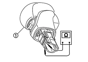
Condition
Continuity
Drive sport mode switch is depressed
Existed
Drive sport mode switch is depressed
Not existed
Is the inspection result normal?
YES >>INSPECTION END
NO >>Replace selector lever knob. Refer to Removal and Installation.
Other materials:
Sonar System. Preparation. Preparation
Preparation
Special Service Tools
Special Service Tools
The actual shape of the tools may differ from
those illustrated here.
Tool number
(TechMate No.)
Tool name
D ...
Rear Bumper
Exploded View
Exploded View
EXCEPT FOR SR
1.
Rear bumper side bracket (LH)
2.
Rear bumper reinforcement support
(L ...
Trip computer
1. Vehicle speed
The vehicle speed screen shows the current speed of the Nissan Sentra as well
as the average vehicle speed calculated since the last reset.
Average vehicle speed:
Press the OK button on the steering wheel to open the drive computer Reset menu,
then follow the on-screen in ...