Nissan Sentra B18 (2020-2025) Service Manual: Rear Bumper
Exploded View
Exploded View
EXCEPT FOR SR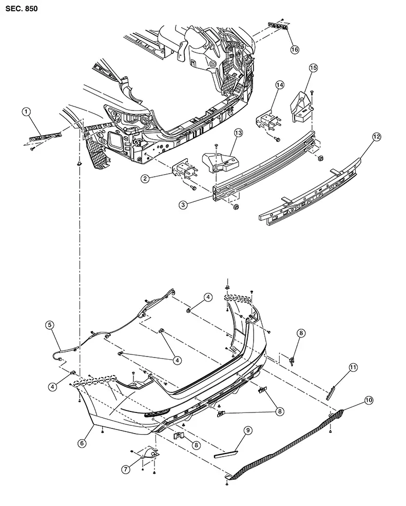
|
1. |
Rear bumper side bracket (LH) |
2. |
Rear bumper reinforcement support (LH) |
3. |
Rear bumper reinforcement |
|
4. |
Sonar sensor |
5. |
Rear bumper harness |
6. |
Rear bumper fascia |
|
7. |
Exhaust finisher |
8. |
Sonar sensor |
9. |
Rear bumper fascia reflector (LH) |
|
10. |
Rear bumper finisher |
11. |
Rear bumper fascia reflector (RH) |
12. |
Rear bumper energy absorber |
|
13. |
Rear bumper energy absorber upper (LH) |
14. |
Rear bumper reinforcement support (RH) |
15. |
Rear bumper energy absorber upper (RH) |
|
16. |
Rear bumper side bracket (RH) |
|
Pawl |
|
1. |
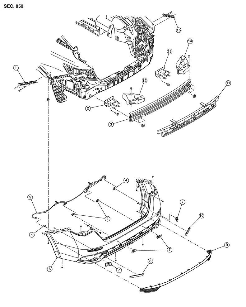
Rear bumper side bracket (LH) |
2. |
Rear bumper reinforcement support (LH) |
3. |
Rear bumper reinforcement |
|
4. |
Sonar sensor |
5. |
Rear bumper harness |
6. |
Rear bumper fascia |
|
7. |
Sonar sensor |
8. |
Rear bumper fascia reflector (LH) |
9. |
Rear bumper finisher |
|
10. |
Rear bumper fascia reflector (RH) |
11. |
Rear bumper energy absorber |
12. |
Rear bumper energy absorber upper (LH) |
|
13. |
Rear bumper reinforcement support (RH) |
14. |
Rear bumper energy absorber upper (RH) |
15. |
Rear bumper side bracket (RH) |
|
|
Pawl |
Removal and Installation
Removal and Installation
CAUTION:
Rear bumper fascia is made of resin. Use care when handling to prevent damage. Avoid contact with oily substances.
REMOVAL
Remove rear combination lamp (body side) (LH/RH). Refer to Removal and Installation (Halogen Headlamp), or Removal and Installation (LED Headlamp).
Remove clip (A) and bolt (B) (LH/RH). 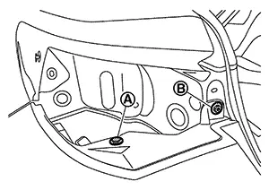
Remove screw [A (LH/RH)]. 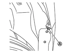
Remove screw [A (LH/RH)]. 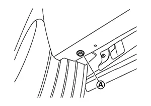
Remove clips (A). 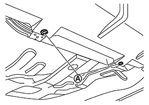
Disconnect rear bumper harness connector.
To release pawls, pull rear bumper
fascia outward in the sequence shown (LH/RH).
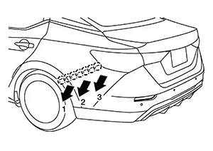
 : Pawl
Remove rear bumper fascia from Nissan Sentra vehicle.
CAUTION:
When removing rear bumper fascia, two workers are required to prevent damage.
Remove rear bumper energy absorbers.
Remove nuts and rear bumper reinforcement. Refer to Exploded View.
Remove bolts and rear bumper reinforcement support (LH/RH). Refer to Exploded View.
Remove rear bumper side bracket (LH/RH) (if necessary).
Remove the following parts after removing rear bumper fascia (if necessary):
-
Rear bumper harness
-
Sonar sensors
-
Rear bumper reflector (LH/RH)
-
Rear bumper finisher
-
Exhaust finisher (if equipped)
INSTALLATION
Installation is in the reverse order of removal.
Note:
After installation, perform the following action tests to confirm proper system operation:
-
Blind Spot Warning. Refer to Work Procedure.
-
Rear Cross Traffic Alert (RCTA). Refer to Work Procedure.
-
The following table shows the specified values for checking normal installation status.
-
Fitting adjustment cannot be performed.
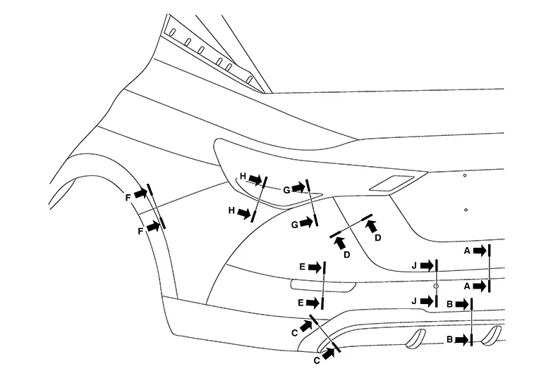 Unit: mm (in)
 |
Section |
Measurement |
Minimum |
Target Value |
Maximum |
|---|---|---|---|---|
|
A-A |
Clearance |
4.8-4.9 (0.189-0.193) |
7.0-7.1 (0.276-0.280) |
9.2-9.3 (0.362-0.366) |
|
B-B |
Clearance |
0.3-0.4 (0.012-0.016) |
1.3-1.4 (0.051-0.055) |
2.3-2.4 (0.091-0.094) |
|
C-C |
Clearance |
0.0-0.2 (0.0-0.008) |
1.2-1.4 (0.047-0.055) |
2.4-2.6 (0.094-0.102) |
|
D-D |
Clearance |
2.1-2.2 (0.083-0.087) |
4.1-4.2 (0.161-0.165) |
6.1-6.2 (0.240-0.244) |
|
E-E |
Clearance |
0.5-0.6 (0.020-0.024) |
1.5-1.6 (0.059-0.063) |
2.5-2.6 (0.098-0.102) |
|
F-F |
Clearance |
0.0 (0.0) |
0.3 (0.012) |
1.1 (0.043) |
|
F-F |
Surface height |
-0.3 (-0.01) |
0.7 (0.028) |
1.7 (0.067) |
|
G-G |
Clearance |
0.3 (0.012) |
2.0 (0.079) |
3.9 (0.154) |
|
H-H |
Clearance |
0.2 (0.008) |
1.9 (0.075) |
3.8 (0.150) |
|
J-J |
Clearance |
0.0-0.1 (0.0-0.004) |
0.5-0.6 (0.020-0.024) |
1.0-1.1 (0.039-0.043) |
|
J-J |
Surface height |
0.0-0.1 (0.0-0.004) |
0.5-0.6 (0.020-0.024) |
1.0-1.1 (0.039-0.043) |
-
The following table shows the specified values for checking normal installation status.
-
Fitting adjustment cannot be performed.
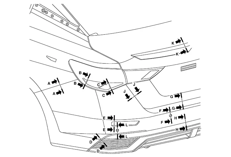 Unit: mm (in)
 |
Section |
Measurement |
Minimum |
Target Value |
Maximum |
|---|---|---|---|---|
|
A-A |
Clearance |
0.0 (0.0) |
0.3 (0.012) |
1.1 (0.043) |
|
Surface height |
-0.3 (-0.01) |
0.7 (0.028) |
1.7 (0.067) |
|
|
B-B |
Clearance |
0.3 (0.012) |
2.0 (0.079) |
3.9 (0.154) |
|
C-C |
Clearance |
0.3 (0.012) |
2.0 (0.079) |
3.9 (0.154) |
|
D-D |
Clearance |
0.3 (0.012) |
1.3 (0.051) |
2.3 (0.091) |
|
E-E |
Clearance |
0.5 (0.020) |
1.5-1.6 (0.059-0.063) |
2.6 (0.102) |
|
F-F |
Clearance |
0.0 (0.0) |
0.5 (0.020) |
1.0 (0.039) |
|
Surface height |
-0.5 (-0.02) |
0.0-0.5 (0.0-0.020) |
1.0 (0.039) |
|
|
G-G |
Clearance |
4.8 (0.189) |
7.0-7.1 (0.276-0.280) |
9.3 (0.366) |
|
H-H |
Clearance |
0.1 (0.004) |
1.6 (0.063) |
3.1 (0.22) |
|
J-J |
Clearance |
2.1 (0.083) |
4.1-4.2 (0.161-0.165) |
6.2 (0.244) |
|
K-K |
Clearance |
0.1 (0.004) |
1.0 (0.039) |
1.9 (0.075) |
|
L-L |
Clearance |
0.0 (0.0) |
0.5 (0.020) |
1.0 (0.039) |
|
Surface height |
-0.5 (-0.02) |
0.0-0.5 (0.0-0.020) |
1.0 (0.039) |
Other materials:
P0102 Maf Sensor
Dtc Description
DTC Description
DTC DETECTION LOGIC
DTC
CONSULT screen terms
(Trouble diagnosis
content)
DTC detection
condition
...
Periodic Maintenance
Headlamp Aiming Adjustment
Aiming Adjustment
Aiming Adjustment
PREPARATION BEFORE ADJUSTING
Before performing aiming adjustment, check the
following:
Ensure all tires are inflated to correct
pressure.
Place Nissan Sentra vehicle and screen on l ...
Combination Meter
Values on the Diagnosis Tool
Values on the
Diagnosis Tool
Note:
The following table includes information (items)
inapplicable to this Nissan Sentra vehicle. For information (items) applicable to
this vehicle, refer to CONSULT display items.
...