Nissan Sentra B18 (2020-2025) Service Manual: Cvt Fluid Temperature Sensor
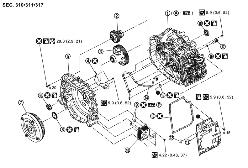
Exploded View
Exploded View
|
|
Transaxle assembly |
|
Reduction gear assembly |
|
Differential assembly |
|
|
Baffle plate C |
|
Converter housing |
|
Differential side oil seal |
|
|
Torque converter |
|
Converter housing oil seal |
|
O-ring |
|
|
CVT oil warmer |
|
Control valve cover |
|
Clip |
|
|
Control valve cover gasket |
|
CVT fluid temperature sensor |
|
O-ring |
|
|
O-ring |
|
Primary speed sensor |
|
Differential side oil seal |
 |
Converter housing installation surface of the transaxle case |
||||
|
|
: Always replace after every disassembly. |
||||
|
|
: N·m (kg-m, ft-lb) |
||||
|
|
: N·m (kg-m, in-lb) |
||||
|
|
: Apply CVT fluid |
||||
|
|
: Apply petroleum jelly |
||||
|
|
: Apply Loctite 5460 or equivalent |
||||


Disassembly and Assembly
Disassembly and Assembly
DISASSEMBLY
Remove the drain plug from transaxle case and then drain the CVT fluid. Refer to Removal and Installation.
Remove the transaxle assembly from the Nissan Sentra vehicle. Refer to Removal and Installation.
Remove drain plug O-ring.
Maintain the same posture as on the
Nissan Sentra vehicle. Note: 
Use plastic or wood blocks to stabilize the transaxle assembly on the work bench if needed.
Remove torque converter from transaxle
assembly. Note:
Wipe out remaining CVT fluid in torque converter.
CAUTION:
-
While removing torque converter, never damage the bush in the sleeve of torque converter.
-
Completely drain CVT fluid from torque converter by tilting right and left several times until no fluid coming out.
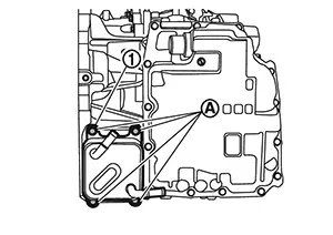
Remove the CVT oil warmer mounting bolts
and then remove CVT oil warmer  .
.
Remove O-rings
from CVT oil warmer. 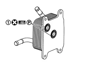
Remove primary speed sensor mounting bolt
and then remove primary speed sensor . 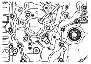
Remove O-ring
from primary speed sensor. 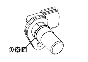
Remove differential side oil seal
from transaxle assembly. 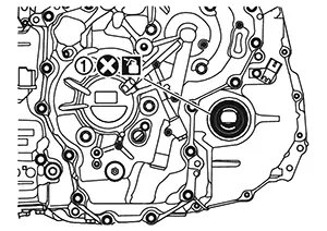
Place transaxle assembly with the converter housing side as the top.
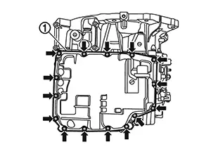
Remove the control valve cover mounting
bolts ( 15 pieces) and then remove control valve cover
.
15 pieces) and then remove control valve cover
. 
Remove clip
from terminal assembly. 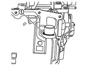
Remove the terminal assembly
from control valve cover. 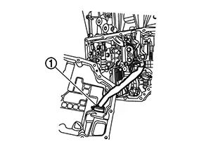
CAUTION:
Never disconnect the connector of the terminal assembly.
When the connector is disconnected, replacement with new control valve assembly is required. 
Remove O-ring
from terminal assembly. 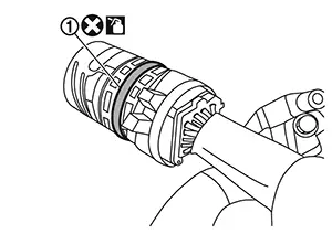
Remove the control valve cover gasket . 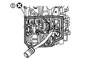
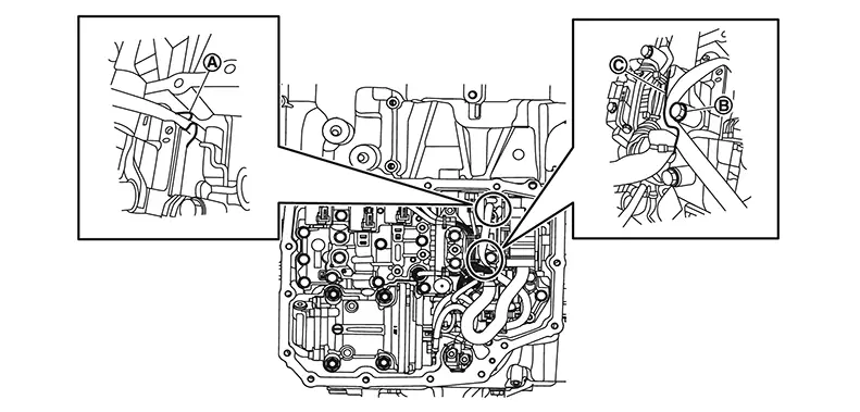
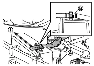
Disconnect CVT fluid temperature sensor
harness connector . 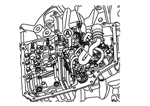
Remove the CVT fluid sensor harness according to the following procedure.
-
Remove harness from the notch
of the control valve plate. -
Remove harness from between the bolt
 and the bracket
  .
.
Remove converter housing mounting bolts (
20 pieces). 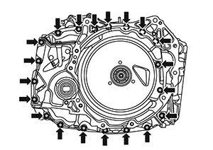
Remove converter housing by applying slide
hammer [SST: KV315J0610 (NI-25721-A)], slide hammer nut and bolt kit
[SST: KV315J0630 (NI-50255-UPD)] and J hook case separator [SST:
KV315J0620 (NI-51923)] to three positions with arrow marks (). 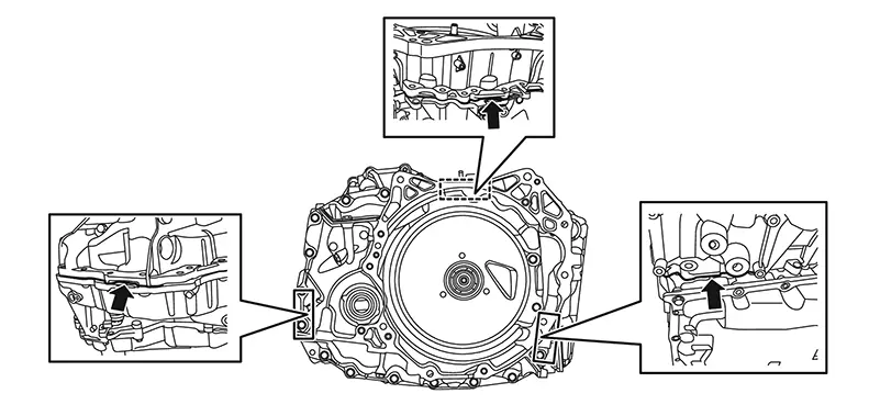
Remove mounting bolts (
3 pieces) and then remove the baffle plate C  from the converter
housing.
from the converter
housing. 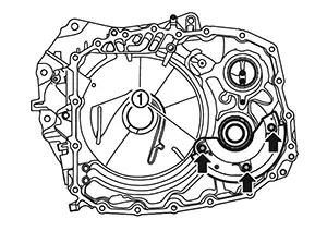
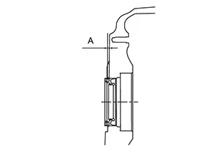
Remove differential side oil seal
from converter housing using a suitable tool (A). 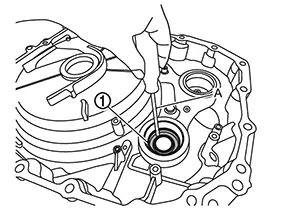
Remove converter housing oil seal
from converter housing using a suitable tool (A). 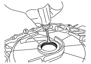
Remove reduction gear assembly and differential assembly  together.
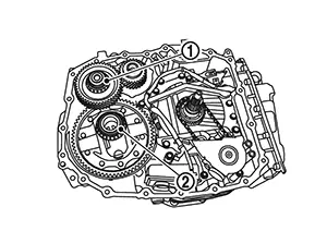
CAUTION:
Handle parts with care. Never reuse damaged parts, if dropped.
Remove harness clips . 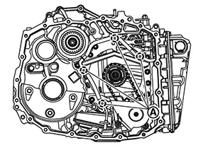
CAUTION:
Do not cut the clip or pull it out forcefully, but pull it out by pinching its claw.
Note:
Use pliers with curved ends for easy work.
Disconnect the harness connector
from the input speed sensor. 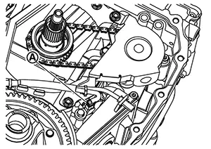
Remove CVT fluid temperature sensor from the oil strainer.
Thoroughly clean the mating surfaces of
the transaxle case and torque converter housing. Note:
-
A plastic scraper can be used.
-
Remove the old sealant from the mating surfaces.
CAUTION:
-
Never use sanding discs, similar abrasive tools, or metal blades.
-
Use parts cleaner or equivalent solvent and lint-free paper only.
-
Make sure the parts cleaner or solvents used are compatible with local regulations.
-
Prevent debris from entering in the transaxle assembly.
ASSEMBLY
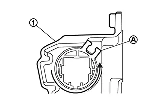
Fix the CVT fluid temperature sensor body
to the oil strainer by the clip .
 Note:
Note:
Fix the CVT fluid temperature sensor at the center
notch of three notches on the CVT temperature
sensor body.
Place the CVT fluid temperature sensor harness with the following procedure.
-
: Put the harness into the control valve
room through the opening of transaxle case.
-
: The harness shall be placed between the
dummy cover and the manual shaft retaining pin.
-
: The harness shall be placed between the
dummy cover and the transaxle case.
CAUTION:
The harness shall not be placed on the bolts.
-
 : The harness shall be placed between the
bolt and the dummy cover.
: The harness shall be placed between the
bolt and the dummy cover. -
 : The harness shall be placed between
guide walls on the dummy cover.
: The harness shall be placed between
guide walls on the dummy cover.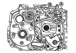
Install reduction gear assembly
and differential assembly
together.
CAUTION:
Handle parts with care. Never reuse damaged parts, if dropped.
Install baffle plate C
to the converter housing and then tighten baffle plate C mounting bolts
( 3 pieces) to the specified torque. Refer to Exploded View. 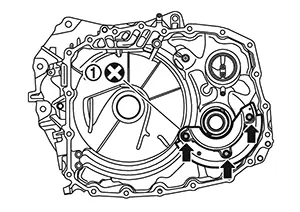
CAUTION:
Never reuse baffle plate C.
Apply Loctite 5460 or equivalent on the converter housing installation surface of the transaxle case.
CAUTION:
-
Completely remove all moisture, oil and old sealant, etc. from the transaxle case and converter housing mounting surfaces.
-
The sealant width is 2 - 3 mm (0.08 - 0.12 in).
-
Check that the starting point and the ending point are about the middle between the bolts. The overlap both ends of the bead
by 25 - 30 mm (0.98 - 1.18
in).
Install converter housing.
CAUTION:
Completely remove all moisture, oil and old sealant, etc. from the transaxle case and converter housing mounting surfaces.
Tighten converter housing mounting bolts
to the specified torque in numerical order shown in the figure. Refer to
Exploded View. 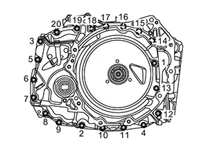 Note:
Note:
Apply CVT fluid to the bolts when installing.
CAUTION:
Never reuse the converter housing mounting bolts.
Place the CVT fluid temperature sensor harness with the following procedure.
-
The harness shall pass through the notch
of the plate of control
valve. -
The harness shall pass through between the bolt
and the bracket on the
control valve.
Connect CVT fluid temperature sensor
harness connector .
Install control valve cover gasket .
CAUTION:
Never reuse the control valve cover gasket.
Install O-ring
to terminal assembly.
CAUTION:
-
Never reuse the O-ring.
-
Apply CVT fluid to the O-ring.
Install the terminal assembly
to control valve cover. Note:
Turn the terminal assembly until its locator touches the control valve
cover .
Install clip
to terminal assembly.
Install the control valve cover. 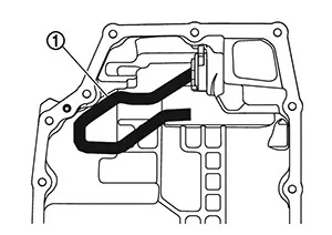 Note:
Note:
The control valve harness must be wired as shown figure.
CAUTION:
Be secure that the harness is not twisted unnecessarily.
Tighten control valve cover mounting bolts
to the specified torque in numerical order shown in the figure. Refer to
Exploded View. 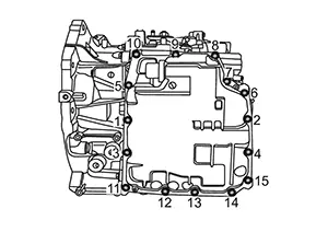
CAUTION:
Apply CVT fluid to the bolts when installing.
Install O-ring
to drain plug. 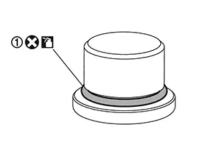
CAUTION:
-
Never reuse the O-ring.
-
Apply CVT fluid to the O-ring.
Install drain plug
and then tighten drain plug to the specified torque. Refer to Exploded View. 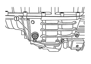
Maintain the same posture as on the Nissan Sentra vehicle.
Install each differential side oil seal evenly using following tools.
CAUTION:
-
Never reuse differential side oil seals.
-
Apply CVT fluid to differential side oil seals.
|
Location |
Special Service Tools |
|---|---|
|
Converter housing side |
|
|
Transaxle case side |
|
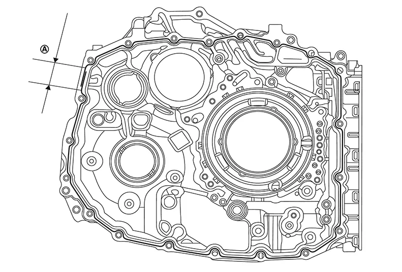
Install differential side oil seal with seal installer until it is flush.
|
Height or depth (A) of differential side oil seal from the converter housing surface |
: 2.2±0.5 mm (0.087±0.020 in) |
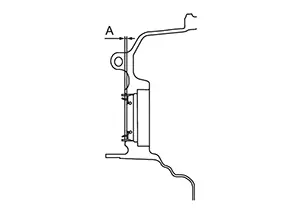
|
Height or depth (A) of differential side oil seal from the transaxle case surface |
: 1.8±0.5 mm (0.071±0.020 in) |
Install O-ring
to primary speed sensor.
CAUTION:
-
Never reuse the O-ring.
-
Apply CVT fluid to the O-ring.
Install primary speed sensor
and then tighten primary speed sensor mounting bolt
to the specified tightening torque. Refer to Exploded View.
Install O-rings
to CVT oil warmer.
CAUTION:
-
Never reuse the O-rings.
-
Apply petroleum jelly to the O-rings.
Install CVT oil warmer
to converter housing and then tighten CVT oil warmer mounting bolts
to the specified torque. Refer to Exploded View.
Install the new converter housing oil seal. Refer to Disassembly and Assembly.
Install torque converter to transaxle assembly. Refer to Disassembly and Assembly.
Install the transaxle assembly to the Nissan Sentra vehicle. Refer to Removal and Installation.
Fill the CVT fluid. Refer to Refilling.
Other materials:
Intelligent Key Button Operation Has Poor Range (all Keys)
Description
Description
Intelligent Key button operation has poor
range.
SYMPTOM TABLE (BOTH INTELLIGENT KEYS HAVE
THE SAME SYMPTOMS)
Door lock operation (remote
keyless entry)
...
Unit Removal and Installation. Transaxle Assembly
Transaxle Assembly
Exploded View
Exploded View
1.
CVT fluid charging pipe cap
2.
CVT fluid charging pipe
...
U2140-87 Can Comm Err (ecm)
Dtc Description
DTC Description
DESCRIPTION
CAN (Controller Area Network) is a serial communication
line for real time applications. It is an on-Nissan Sentra vehicle multiplex communication
line with high data communication speed and excellent error detection
ability. Modern Nissan ...