Nissan Sentra B18 (2020-2025) Service Manual: Unit Removal and Installation. Transaxle Assembly
Transaxle Assembly
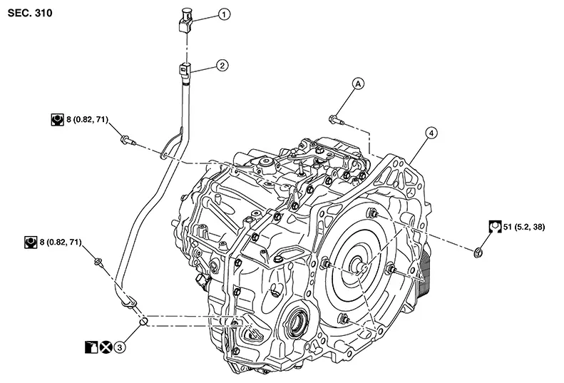
Exploded View
Exploded View
|
1. |
CVT fluid charging pipe cap |
2. |
CVT fluid charging pipe |
3. |
O-ring |
|
4. |
Transaxle assembly |
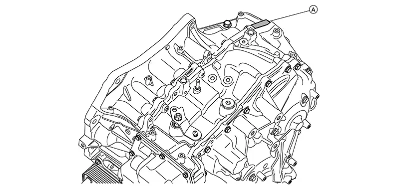
A. |
Refer to Removal and Installation. |
Removal and Installation
Removal and Installation
REMOVAL
Warning:
Do not remove the radiator cap when the engine is hot. Serious burns could occur from high pressure coolant escaping from the radiator. Wrap a thick cloth around the cap. Slowly turn a quarter turn to allow built-up pressure to escape. Carefully remove the cap by turning it all the way.
CAUTION:
-
Perform when the engine is cold.
-
When replacing the transaxle assembly, perform "ADDITIONAL SERVICE WHEN REPLACING TRANSAXLE ASSEMBLY". Refer to Description.
-
When replacing TCM and transaxle assembly simultaneously, perform “ADDITIONAL SERVICE WHEN REPLACING TCM AND TRANSAXLE ASSEMBLY” before work. Refer to Description.

When removing components such as hoses, tubes/lines, etc., cap or plug openings to prevent fluid from spilling.
Remove CVT drain plug and drain CVT fluid.
CAUTION:
Do not reuse O-ring.
Remove engine and transaxle assembly. Refer to Removal and Installation.
Separate the engine from the transaxle
assembly. Refer to Removal and Installation.
Note:
Using paint, put matching marks on the drive plate and torque converter when removing the torque converter to drive plate nuts.
INSTALLATION
Note the following and installation is in the reverse order of removal.
CAUTION:
-
Write down the serial number of the new transaxle assembly.
-
When replacing an engine or transaxle you must make sure any dowels are installed correctly during re-assembly
-
Improper alignment caused by missing dowels may cause vibration, oil leaks or breakage of drive train components.
-
Do not reuse O-rings or copper sealing washers.
-
When turning crankshaft, turn it clockwise as viewed from the front of the engine.
-
When tightening the nuts for the torque converter while securing the crankshaft pulley bolt, be sure to confirm the tightening torque of the crankshaft pulley bolt. Refer to Exploded View.
-
After converter is installed to drive plate, rotate crankshaft several turns to check that CVT rotates freely without binding.
-
When installing the CVT to the engine, align the matching mark on the drive plate with the matching mark on the torque converter.
-
When installing the drive plate to torque converter nuts, tighten them temporarily. Then tighten the nuts to the specified torque. Refer to Exploded View.
-
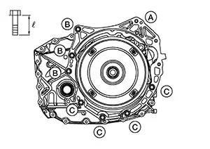
Install the transaxle assembly and engine assembly mounting bolts according to the following standards.
Note:
Do not lubricate engine assembly mounting bolts.
Bolt symbol
(A)
(B)
(C)
Insertion direction
Transaxle to cylinder block
Cylinder block to transaxle
Oil pan to transaxle
Quantity
1
3
4
Bolt length
“
 ” mm (in)
55 (2.17)
50.5 (1.988)
50.5 (1.988)
Tightening torque
N·m (kg-m, ft-lb)
62.0 (6.3, 46)
After replacing transaxle assembly, perform "ADDITIONAL SERVICE WHEN REPLACING TRANSAXLE ASSEMBLY". Refer to Description.
Inspection and Adjustment
Inspection and Adjustment
INSPECTION BEFORE INSTALLATION
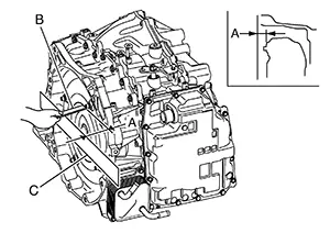
After inserting a torque converter to the CVT, check dimension (A) with in the reference value limit.
|
B |
: Scale |
|
C |
: Straightedge |
|
Dimension (A) |
: Refer to Torque Converter. |
INSPECTION AFTER INSTALLATION
Check the following items:
Start the engine and check visually that there is no leakage of CVT fluid and engine coolant.
For CVT position, refer to Inspection.
ADJUSTMENT AFTER INSTALLATION
Adjust the CVT fluid level. Refer to Adjustment.
Other materials:
Squeak and Rattle Trouble Diagnoses
Work Flow
Work Flow
CUSTOMER INTERVIEW
Interview the customer if possible, to determine
the conditions that exist when the noise occurs. Use the Diagnostic
Worksheet during the interview to document the facts and conditions
when the noise occurs and any customer's comments; refer ...
B1019 Occupant Sens
Dtc Description
DTC Description
DESCRIPTION
B1019 OCCUPANT SENS
The OCS control unit is wired to the air bag
diagnosis sensor unit. The air bag diagnosis sensor unit will
monitor the OCS for failures and interruptions in communication
between the OCS control unit and the air bag ...
P27f0-00 Transmission Range Control B Position Sensor/switch
Dtc Description
DTC Description
DTC DETECTION LOGIC
DTC
CONSULT screen terms
(Trouble diagnosis
content)
DTC detection
...