Nissan Sentra B18 (2020-2025) Service Manual: Control Linkage
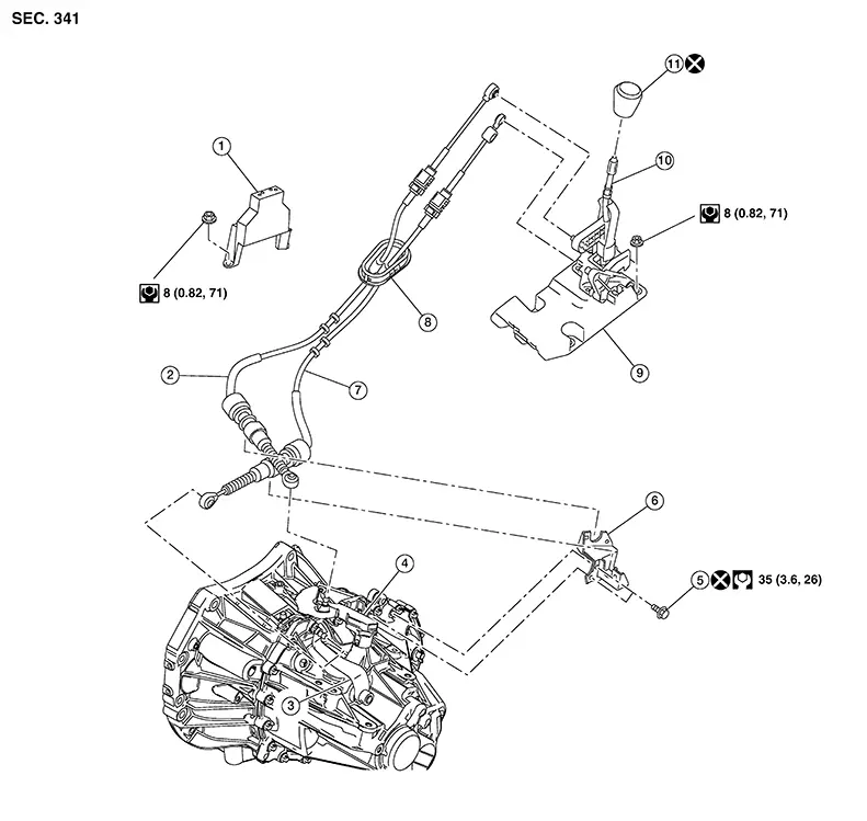
Exploded View
|
1. |
Center console support bracket |
2. |
Selector cable |
3. |
Selector lever |
|
4. |
Shift lever |
5. |
Tapping bolt |
6. |
M/T cable mounting bracket |
|
7. |
Shift cable |
8. |
Grommet |
9. |
M/T shift selector |
|
10. |
Shift selector |
11. |
Shift selector knob |
Removal and Installation
REMOVAL
Move the M/T shift selector to the neutral position.
Remove the battery tray. Refer to Removal and Installation.
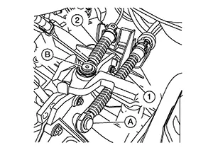
Using a
suitable tool, release cables (1) and (2) from shift levers (A) and
(B).
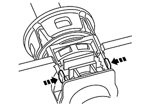
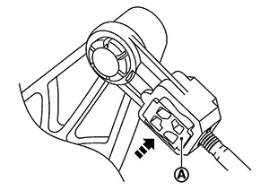
While
pressing the lock of the control linkage cables in the direction
shown, remove the shift cable and selector cable from the M/T cable
bracket.
Remove the M/T shift selector. Refer to Removal and Installation.
Remove the exhaust front tube. Refer to Exploded View.
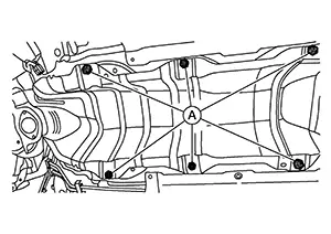
Remove the
nuts (A) and remove the heat shield plate.
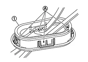
Release
pawls (A) and pull grommet (1) downward to remove.
Remove the shift cable and selector cable from the Nissan Sentra vehicle.
INSTALLATION
Note the following and installation is in the reverse order of removal.
-
Install the selector cable to the shift selector assembly.
-
Move the M/T shift selector to the 4th gear position.
-
Adjust the length (L) between the cable stopper (A) and the M/T shift selector to the standard value.
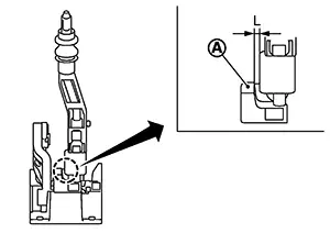
Length (L)
: 3.51 – 4.11 mm (0.1382 – 0.1618 in)
-
Insert the stopper (A) until it reaches the selector cable.
-
Move the shift selector to each gear position to check that there are no bindings. If any, repeat the adjustment of the length between the cable stopper and the shift selector.
CAUTION:
-
Install each cable without causing interference with other parts, a 120 mm (4.72 in)-or-less bend, and a 180-degrees-or-more twist.
-
Install boot of each cable without causing interference with other parts and a 90-degrees-or-more twist.
-
Fit boot of to center console assembly the groove on shift selector knob.
-
To install the shift selector knob, press it into the shift selector.
CAUTION:
-
Do not reuse shift selector knob.
-
Be careful with orientation of shift selector knob.
-
-
Tapping work for tapping bolts is not applied to new transaxle case. Do not perform tapping by other than screwing tapping bolts because tapping is formed by screwing tapping bolts into transaxle case.
CAUTION:
Do not reuse tapping bolt.
-
Insert the each cable until it reaches the cable mounting bracket and shift selector assembly.
-
Move the shift selector to the neutral position.
Inspection
INSPECTION AFTER INSTALLATION
Shift Cable and Select Cable
-
Pull each cable in the removal direction to check that it dose not disconnect from the cable mounting bracket.
-
Pull each cable in the removal direction to check that it dose not disconnect from the shift selector assembly.
-
Pull grommet in the removal direction to check that it dose not disconnect from the Nissan Sentra vehicle.
Shift Selector Assembly and shift selector
-
Check that there is no tangle, hook, abnormal sound, looseness, and interference when the shifter selector is moved to each position. If there is a malfunction, then repair or replace the malfunctioning part.
-
Check that the shifter selector smoothly returns to the neutral position after moving the shift selector from 1st to 2nd gear and moving hands off the shift selector. If there is a malfunction, then repair or replace the malfunctioning part.
-
Check that the shift selector smoothly returns to the neutral position after moving the lever from 5th to 6th gear and moving hands off the shift selector. If there is a malfunction, then repair or replace the malfunctioning part.
 M/t Shift Selector
Exploded View
Exploded View
1.
Ornament
2.
...
 Air Breather Hose
Exploded View
Exploded View
1.
Air breather hose
2.
...
Other materials:
Diagnosis and Repair Workflow
Trouble Diagnosis Flow Chart
Trouble Diagnosis
Flow Chart
DESCRIPTION
DETAIL OF TROUBLE DIAGNOSIS FLOW CHART
INTERVIEW WITH CUSTOMER
Interview with the customer is important to detect
the root cause of CAN communication system errors and to understand
...
Symptom diagnosis
Push-button ignition switch does not operate
Description
Check that vehicle is under the condition shown in “Conditions of vehicle”
before starting diagnosis, and check
each symptom.
Note:
The engine start function, door lock function, power distribution system,
and nats-ivis/nvis ...
Automatic speed control device (ASCD)
AUTOMATIC SPEED CONTROL DEVICE (ASCD) : System Description
SYSTEM DIAGRAM
BASIC ASCD SYSTEM
Refer to Owner's Manual for ASCD operating instructions.
Automatic Speed Control Device (ASCD) allows a driver to keep vehicle at
predetermined constant speed
without depressing accelerator pedal ...
