Nissan Sentra B18 (2020-2025) Service Manual: Removal and Installation
Side Oil Seal
Removal and Installation
Removal and Installation
REMOVAL
Remove front drive shafts. Refer to Removal and Installation (LH)and Removal and Installation (RH).
Remove
differential side oil seals (1) from clutch housing and transaxle
case using a suitable tool. 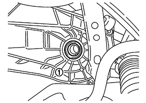
CAUTION:
Do not damage transaxle case and clutch housing.
INSTALLATION
Installation is in the reverse order of removal.
-
Install differential side oil seals (1) to clutch housing and transaxle case, using Tools.
Tool number
: KV32500QAA
Tool number
: B.vi 1666-B
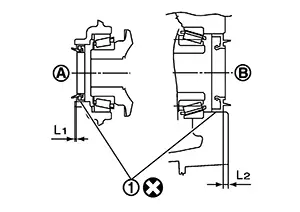
(A)
: Transaxle case side
(B)
: Clutch housing side
Dimension (L1)
: 1.2 – 1.8 mm (0.047 – 0.071 in)
Dimension (L2)
: 2.7 – 3.3 mm (0.106 – 0.130 in)
CAUTION:
-
Do not incline differential side oil seal.
-
Do not damage clutch housing and transaxle case.
-
Inspection
Inspection
Check the oil level and oil leaks. Refer to Inspection.
Park/neutral Position (pnp) Switch (neutral Switch)
Removal and Installation
Removal and Installation
REMOVAL
Remove the air cleaner assembly. Refer to Removal and Installation.
Disconnect harness connector from the park/neutral position (PNP) switch (neutral switch).
Remove
park/neutral position (PNP) switch (neutral switch) from transaxle
case. 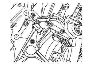
INSTALLATION
Apply recommended sealant to threads of park/neutral position (PNP) switch (neutral switch).
-
Use Genuine Liquid Gasket, Three Bond 1215 or an equivalent. Refer to Recommended Chemical Products and Sealants.
CAUTION:
Remove old sealant and oil adhering to threads.
Install park/neutral position (PNP) switch (neutral switch) to transaxle case.
Tighten park/neutral position (PNP) switch (neutral switch) to the specified torque. Refer to Exploded View.
Installation of the remaining components is in the reverse order of removal.
Inspection
Inspection
Check continuity between position switch terminals. Refer to Component Inspection (Back-up lamp switch) and Component Inspection park/neutral position (PNP) switch (neutral switch).
Check the oil leaks. Refer to Inspection.
M/t Shift Selector
Exploded View
Exploded View
|
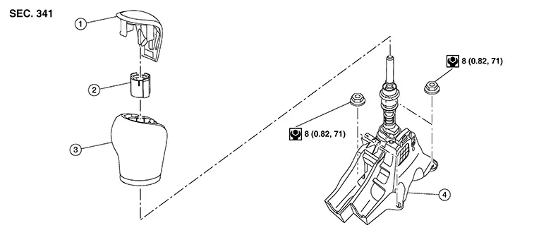
1. |
Ornament |
2. |
Retainer |
3. |
Shift lever knob |
|
4. |
M/T shift selector assembly |
Removal and Installation
Removal and Installation
REMOVAL
Remove the center console assembly. Refer to Removal and Installation.
Remove the center console support bracket. Refer to Exploded View.
Remove
bolts (A) and remove M/T shift selector. 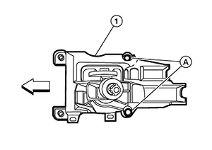
Disconnect and remove shift cable and selector cable from M/T shift selector assembly. Refer to Exploded View.
INSTALLATION
Install in the reverse order of removal.
CAUTION:
Be careful with orientation of shift lever knob.
Control Linkage
Exploded View
Exploded View
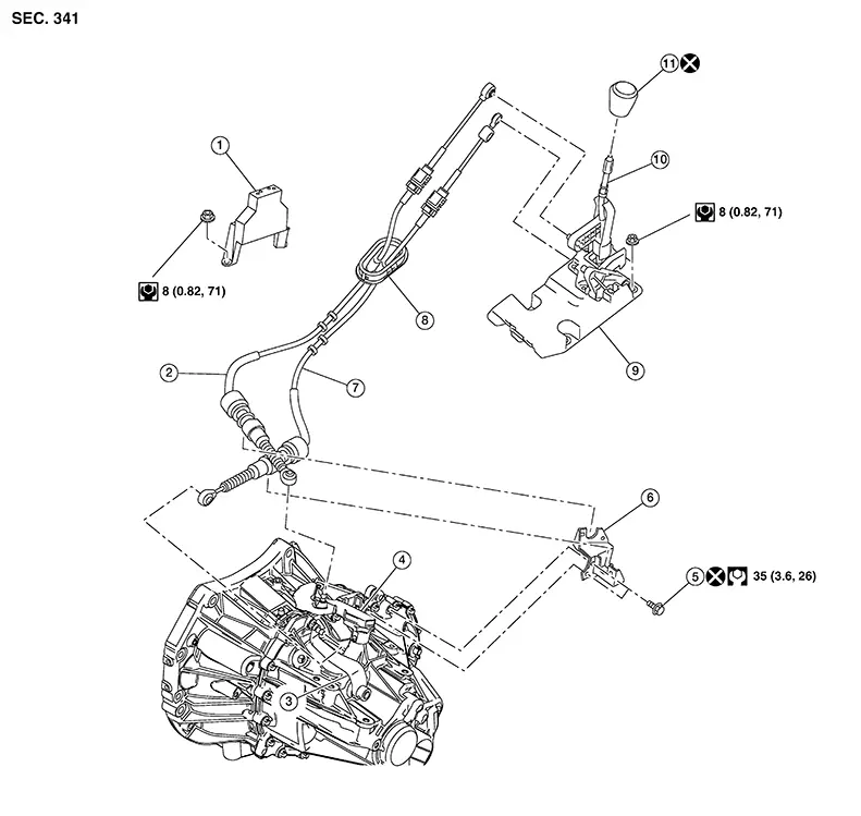
|
1. |
Center console support bracket |
2. |
Selector cable |
3. |
Selector lever |
|
4. |
Shift lever |
5. |
Tapping bolt |
6. |
M/T cable mounting bracket |
|
7. |
Shift cable |
8. |
Grommet |
9. |
M/T shift selector |
|
10. |
Shift selector |
11. |
Shift selector knob |
Removal and Installation
Removal and Installation
REMOVAL
Move the M/T shift selector to the neutral position.
Remove the battery tray. Refer to Removal and Installation.
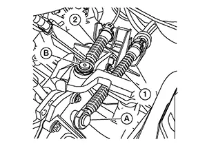
Using a
suitable tool, release cables (1) and (2) from shift levers (A) and
(B).
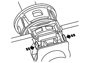
While
pressing the lock of the control linkage cables in the direction
shown, remove the shift cable and selector cable from the M/T cable
bracket.
Remove the M/T shift selector. Refer to Removal and Installation.
Remove the exhaust front tube. Refer to Exploded View.
Remove the
nuts (A) and remove the heat shield plate.
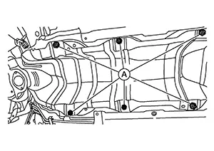
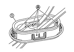
Release
pawls (A) and pull grommet (1) downward to remove.
Remove the shift cable and selector cable from the Nissan Sentra vehicle.
INSTALLATION
Note the following and installation is in the reverse order of removal.
-
Install the selector cable to the shift selector assembly.
-
Move the M/T shift selector to the 4th gear position.
-
Adjust the length (L) between the cable stopper (A) and the M/T shift selector to the standard value.
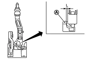
Length (L)
: 3.51 – 4.11 mm (0.1382 – 0.1618 in)
-
Insert the stopper (A) until it reaches the selector cable.
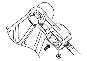
-
Move the shift selector to each gear position to check that there are no bindings. If any, repeat the adjustment of the length between the cable stopper and the shift selector.
CAUTION:
-
Install each cable without causing interference with other parts, a 120 mm (4.72 in)-or-less bend, and a 180-degrees-or-more twist.
-
Install boot of each cable without causing interference with other parts and a 90-degrees-or-more twist.
-
Fit boot of to center console assembly the groove on shift selector knob.
-
To install the shift selector knob, press it into the shift selector.
CAUTION:
-
Do not reuse shift selector knob.
-
Be careful with orientation of shift selector knob.
-
-
Tapping work for tapping bolts is not applied to new transaxle case. Do not perform tapping by other than screwing tapping bolts because tapping is formed by screwing tapping bolts into transaxle case.
CAUTION:
Do not reuse tapping bolt.
-
Insert the each cable until it reaches the cable mounting bracket and shift selector assembly.
-
Move the shift selector to the neutral position.
Inspection
Inspection
INSPECTION AFTER INSTALLATION
Shift Cable and Select Cable
-
Pull each cable in the removal direction to check that it dose not disconnect from the cable mounting bracket.
-
Pull each cable in the removal direction to check that it dose not disconnect from the shift selector assembly.
-
Pull grommet in the removal direction to check that it dose not disconnect from the Nissan Sentra vehicle.
Shift Selector Assembly and shift selector
-
Check that there is no tangle, hook, abnormal sound, looseness, and interference when the shifter selector is moved to each position. If there is a malfunction, then repair or replace the malfunctioning part.
-
Check that the shifter selector smoothly returns to the neutral position after moving the shift selector from 1st to 2nd gear and moving hands off the shift selector. If there is a malfunction, then repair or replace the malfunctioning part.
-
Check that the shift selector smoothly returns to the neutral position after moving the lever from 5th to 6th gear and moving hands off the shift selector. If there is a malfunction, then repair or replace the malfunctioning part.
Air Breather Hose
Exploded View
Exploded View
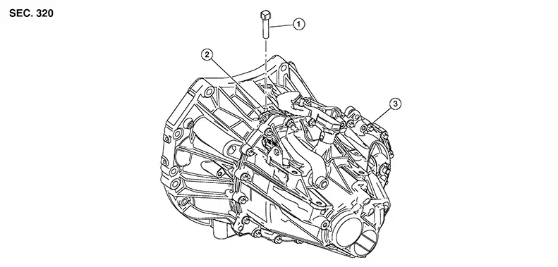
|
1. |
Air breather hose |
2. |
2 way connector |
3. |
Transaxle assembly |
Removal and Installation
Removal and Installation
REMOVAL
Remove air breather hose from the 2 way connector.
CAUTION:
When removing air breather hose, be sure to hold 2 way connector securely.
INSTALLATION
Installation is in the reverse order of removal.
CAUTION:
-
Install air breather hose, preventing crush and clogging caused by bending.
-
Insert the allowance of air breather hose to the spool of the 2 way connector.
-
Securely engage the clips in the hole.
-
Do not reuse clip.
Other materials:
P0960-00 Pressure Control Solenoid a
Dtc Description
DTC Description
DTC DETECTION LOGIC
DTC
CONSULT screen terms
(Trouble diagnosis
content)
DTC detection
conditi ...
Blower Motor
Diagnosis Procedure
Diagnosis Procedure
CHECK FUSE
Ignition switch OFF.
Check 30A fuse [No. 55, located in fuse block
(J/B)].
...
Handling Precautions for Plastics
Precautions for Plastics
Precautions
For Plastics
Abbreviation
Material name
Heat resisting temperature °C
(°F)
Resi ...