Nissan Sentra B18 (2020-2025) Service Manual: Vacuum Pump
Exploded View
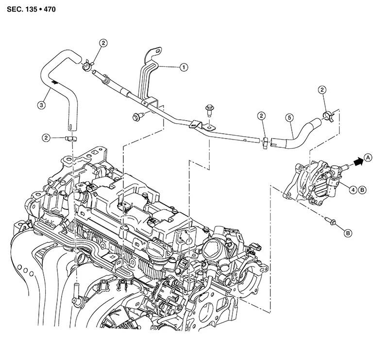
Exploded View
|
1. |
Vacuum tube |
2. |
Clamp |
3. |
Vacuum hose A |
|
4. |
Vacuum pump |
5. |
Vacuum hose B |
A. |
To vacuum hose. Refer to Exploded View. |
|
B. |
Refer to Removal and Installation. |
Removal and Installation
Removal and Installation
REMOVAL
Remove the battery. Refer to Removal and Installation (Battery).
Remove vacuum hose from vacuum pump. Refer to Exploded View.
Remove vacuum hose B from vacuum pump.
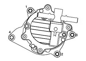
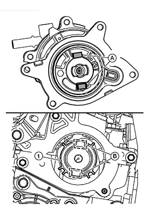
Loosen vacuum pump bolts in
reverse of the sequence shown.
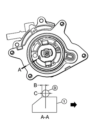
Insert a suitable tool at
location (A) and separate the vacuum pump (1) from the cylinder
head.
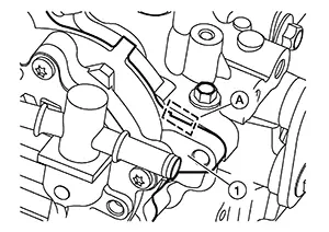
CAUTION:
-
Do not damage the mating surface.
-
The liquid gasket used at the factory is very strong. Pry only in the area shown.
-
Do not disassemble vacuum pump.
Remove the
vacuum tube using the following procedure (if necessary): Remove vacuum hose A from intake
manifold. Remove harness retainer (A) from
vacuum tube (1). 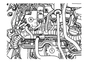 Remove bolts securing
the vacuum
tube. Remove the vacuum tube, vacuum hose
A and vacuum hose B towards the passenger side.
Remove bolts securing
the vacuum
tube. Remove the vacuum tube, vacuum hose
A and vacuum hose B towards the passenger side.
INSTALLATION
Apply a continuous bead of liquid
gasket (D) with a suitable tool to the vacuum pump (1) as
shown.
CAUTION:
-
The components must be installed within 5 minutes of the liquid gasket application.
-
Do not re-tighten bolts after the 5 minutes have elapsed.
-
Use Genuine Silicone RTV Sealant or equivalent. Refer to Recommended Chemical Products and Sealants.
|
(A) |
: View A |
|
(B) |
: 1.5 mm (0.059 in) |
|
(C) |
: 4.0 - 5.0 mm (0.157 - 0.197 in) |
|
|
: Vacuum pump outside |

Install the vacuum pump and
tighten bolts to the specified torque in the sequence shown.
|
Vacuum pump bolts |
: 10 N·m (1.0 kg-m, 89 in-lb) |

Make sure to align the tabs (A) on the back of the vacuum pump with the recesses (B) in the signal plate [INT (1)].
Installation of the remaining components is in the reverse order of removal.
CAUTION:
Since a check valve is built-in inside of vacuum hose A, install vacuum hose A with arrow towards intake manifold.
Other materials:
P052a Intake Valve Timing Control
Dtc Description
DTC Description
DTC DETECTION LOGIC
DTC No.
CONSULT screen terms
(Trouble diagnosis
content)
DTC detecting
condition
...
C1714-7b Low Tire Pressure Rr
Dtc Description
DTC Description
Note:
The Signal Tech II Tool [– (NI-50190)] can be used
to perform the following functions: Refer to the Signal Tech II User
Guide for additional information.
Activate and display TPMS sensor IDs
Display tire pressure rep ...
A/c Switch Assembly Signal Circuit
Diagnosis Procedure
Diagnosis Procedure
CHECK WITH SELF DIAGNOSTIC RESULT FUNCTION
CONSULT
Select “Self Diagnostic Result” mode of “HVAC”.
Check DTC.
...