Nissan Sentra B18 (2020-2025) Service Manual: Unit Removal and Installation. Engine Assembly
Engine Assembly
Exploded View
Exploded View
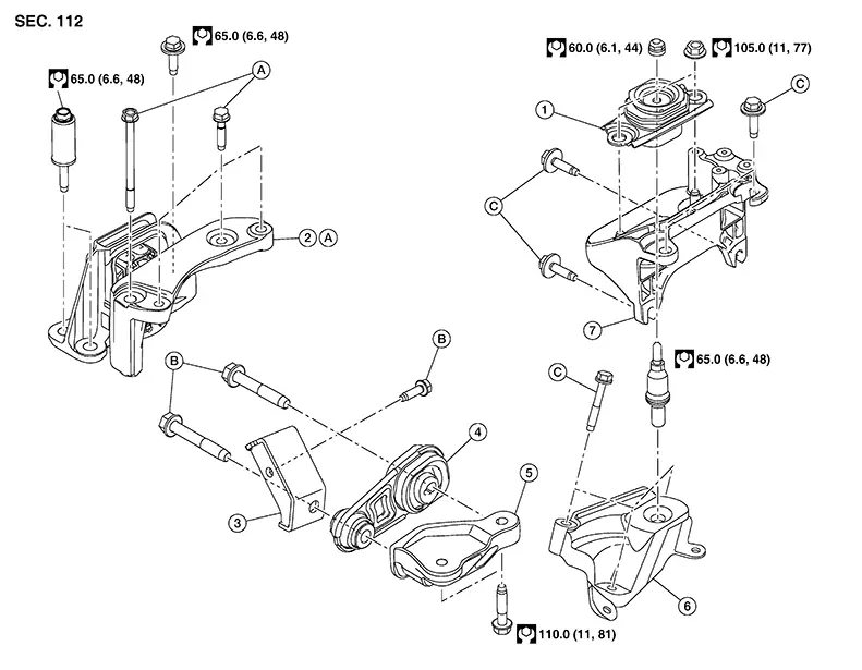
CVT Models
|
1. |
Engine mounting insulator (LH) |
2. |
Engine mounting insulator (RH) |
3. |
Torque rod stay |
|
4. |
Torque rod |
5. |
Torque rod bracket |
6. |
Engine mounting bracket (LH) |
|
7. |
Engine mounting support (LH) |
A. |
Refer to Removal and Installation. |
B. |
Refer to Removal and Installation. |
|
C. |
Refer to Removal and Installation. |
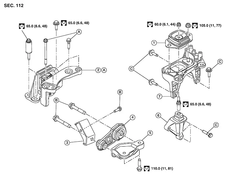
M/T Models
|
1. |
Engine mounting insulator (LH) |
2. |
Engine mounting insulator (RH) |
3. |
Torque rod stay |
|
4. |
Torque rod |
5. |
Torque rod bracket |
6. |
Engine mounting bracket (LH) |
|
7. |
Engine mounting support (LH) |
A. |
Refer to Removal and Installation. |
B. |
Refer to Removal and Installation. |
|
C. |
Refer to Removal and Installation. |
Removal and Installation
Removal and Installation
Warning:
-
Situate the vehicle on a flat and solid surface.
-
Place chocks at front and back of rear wheels.
-
Attach proper slingers and bolts described in PARTS CATALOG if engine slingers are not equipped.
CAUTION:
-
Always be careful to work safely, avoid forceful or uninstructed operations.
-
Do not start working until exhaust system and coolant are cool enough.
-
If items or work required are not covered by the engine section, refer to the applicable sections.
-
Always use the support point specified for lifting.
-
Use either 2-pole lift type or separate type lift as best you can. If board-on type is used for unavoidable reasons, support at the rear axle jacking point with a transmission jack or similar tool before starting work, in preparation for the backward shift of center of gravity.
-
For supporting points for lifting and jacking point at rear axle, refer to Garage Jack and Safety Stand and 2-Pole Lift.

When removing components such as hoses, tubes/lines, etc., cap or plug openings to prevent fluid from spilling.
REMOVAL
Release the fuel pressure. Refer to Work Procedure.
Drain the engine coolant from radiator. Refer to Draining.
CAUTION:
Perform this step when the engine is cold.
Remove the front suspension member. Refer to Removal and Installation.
Remove the drive belt. Refer to Removal and Installation.
Disconnect the harness connectors from the compressor.
Remove the bolts securing the compressor
and move aside. Refer to Exploded View.
Note:
-
The high pressure flexible hose and low pressure flexible hose do not need to be disconnected from compressor.
-
Make sure to support compressor with a suitable tool.
Disconnect the battery. Refer to Battery Disconnect.
Remove the air cleaner assembly and air duct and resonator assembly. Refer to Removal and Installation.
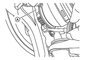
Remove bolt (B) and reposition the
ground harness (A). 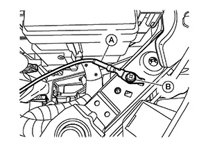
Disconnect the harness connectors from the ECM.
Remove IPDM E/R cover A. Refer to Exploded View.
Release pawls and remove IPDM E/R
harness cover B (1). 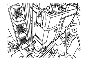
|
|
: Pawl |

Reposition cover (A) and remove
nut (B).  Release pawl and reposition
harness
and fuses.
Release pawl and reposition
harness
and fuses.
|
|
: Pawl |
Remove the IPDM E/R from the IPDM E/R case. Refer to Exploded View.
Disconnect the harness connectors
(A) from the IPDM E/R. 
Release pawls and remove IPDM E/R
harness cover D (1). 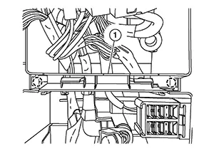
Remove harness retainers (A) from
engine harness cover. 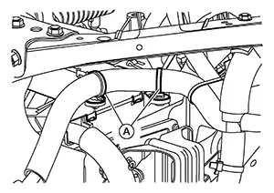
Disconnect the harness connectors from the cooling fan motor and cooling fan module.
Remove harness retainers from cooling fan assembly.
Disconnect the harness connectors
(A) from the TCM and electric intake valve timing control module,
then release harness retainers.Harness Connector (Lever Locking Type). 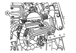
Remove bolts from TCM bracket and position TCM aside. Refer to Exploded View.
Reposition engine harness through opening behind head lamp assembly.
Remove the vacuum hose from the vacuum pump. Refer to Exploded View.
Remove the fuel pump connector protector. Refer to Exploded View.
Disconnect quick connector (A) using
the following procedure: 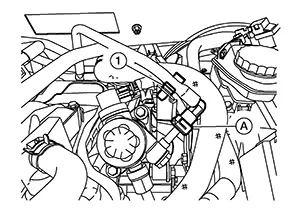 Disconnect fuel
feed hose from
clamp (1). Disengage (A) and pull up (B)
the pawl of the fuel feed hose connector retainer (C) to disconnect
the fuel feed hose from high pressure fuel pump.
Disconnect fuel
feed hose from
clamp (1). Disengage (A) and pull up (B)
the pawl of the fuel feed hose connector retainer (C) to disconnect
the fuel feed hose from high pressure fuel pump. 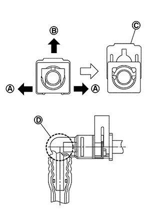 Note:
Note:
If the fuel feed hose is stuck, hold the fuel feed hose by hand and disconnect it by pushing and pulling.
CAUTION:
-
Keep parts away from heat source. Especially, be careful when welding is performed around them.
-
Do not expose parts to battery electrolyte or other acids.
-
Do not bend or twist connection between quick connector and fuel feed hose during installation/removal.
-
Pull quick connector while holding at location (D).
-
Do not remove the retainer.
-
Prepare a tray beforehand to catch fuel that leaks out.
-
Do not pull with lateral force applied. O-ring inside quick connector may be damaged.
Retainer color
: Red
-
To prevent damage to each joint and protect it from the entry of foreign matter, cover the joint with plastic bag (A) or an equivalent.
Disconnect the EVAP hose from the vacuum delay valve. Refer to Exploded View.
Remove the heater hoses from the water outlet. Refer to Exploded View.
Remove the fusible link cover and remove the positive battery cable. Refer to Exploded View.
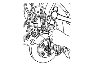
For M/T models, disconnect the control
linkage using the following procedure: Disconnect each cable from the
selector lever (A) and the shift lever (B) using a suitable tool. 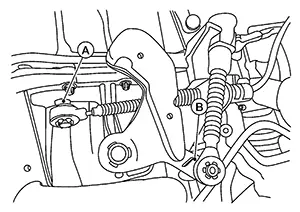 While pressing the locks of the
selector cable in the direction of the arrow shown, remove the selector
cable from the M/T cable bracket.
While pressing the locks of the
selector cable in the direction of the arrow shown, remove the selector
cable from the M/T cable bracket. 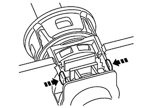
For M/T models, disconnect the clutch
tube from the CSC (Concentric Slave Cylinder) using the following
procedure: Drain the clutch fluid. Refer
to Draining. Press the lock pin (1) into the
bleeding connector of the CSC (Concentric Slave Cylinder) (2), and
then remove clutch tube (3) from CSC. 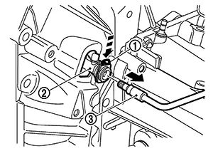
For CVT models, disconnect the control
cable using the following procedure: Using a suitable tool, disconnect
control cable (1) from manual lever as shown ( ).
). 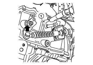 While pressing the locks of the
control cable in the direction shown, remove the control cable from
the CVT cable bracket.
While pressing the locks of the
control cable in the direction shown, remove the control cable from
the CVT cable bracket. 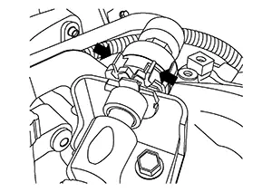
Remove the radiator hose (upper) from the water outlet.
Remove harness retainer from bracket and remove the radiator hose (upper) bracket from the intake manifold. Refer to Exploded View.
Remove the radiator hose (lower) and water hose from the water pump housing. Refer to Exploded View.
Remove the front exhaust tube. Refer to Exploded View.
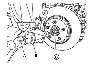
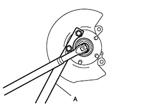
Using hammer (A) and Tool (B) release
staked area (C) of wheel hub lock nut (D).
|
Tool (B) number |
: (NI-52982) |
Visually verify that staked area (A) of wheel hub lock nut (B) is completely released from front drive shaft (1) or damage to drive shaft can occur.
Warning:
To avoid risk of death or severe personal injury:
-
Be sure that staked area of wheel hub lock nut is fully released or damage to drive shaft can occur.
-
Do not damage front drive shaft threads.
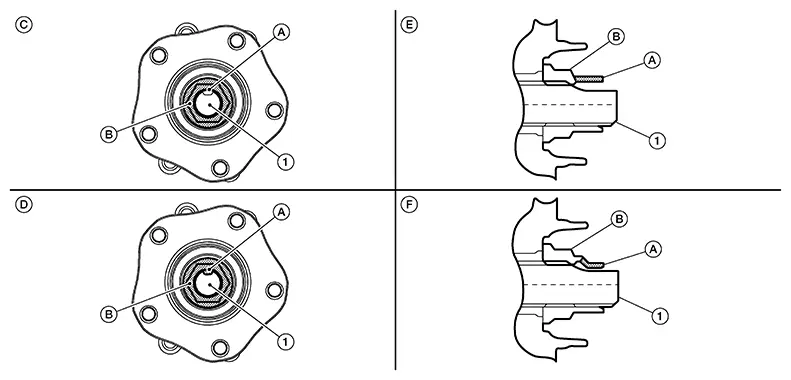
|
(C) |
: Fully released |
|
(D) |
: Not fully released |
|
(E) |
: Fully released (sectional view) |
|
(F) |
: Not fully released (sectional view) |
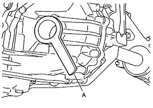
Hold the wheel hub and bearing using
Tool (A). Loosen the wheel hub lock nut (RH/LH).
|
Tool (A) number |
: KV40104000 (ŌĆāŌĆöŌĆā) |
Warning:
To avoid risk of death or severe personal injury:
-
Do not use power tool.
-
Do not damage front drive shaft threads.
-
Do not reuse drive shaft lock nut.
-
When loosening lock nut, if it does not turn smoothly, verify that staked area is completely released.
Using a piece of wood and a suitable
tool, tap on the wheel hub lock nut to disengage the drive shaft from
the wheel hub and bearing. 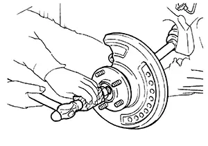
CAUTION:
-
Do not place the drive shaft joint at an extreme angle. Also be careful not to overextend slide joint.
-
Do not allow the drive shaft to hang down without support.
Use a suitable puller if the drive shaft cannot be separated from the wheel hub and bearing even after performing the above procedure.
Remove the wheel hub lock nut (RH/LH).
Remove the bolts and the support bearing retainer (RH only). Refer to Exploded View.
Remove the drive shaft from the
wheel hub and bearing. 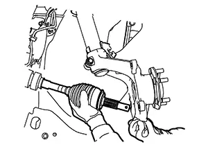
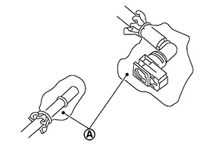
Insert the Tool (A) between the
shaft and the transaxle. Remove the drive shaft from the transaxle. 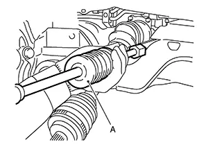
CAUTION:
Confirm that the circular clip is attached to the drive shaft.
|
Tool (A) |
: Drive shaft joint puller (Commercially available) |
Remove the differential side oil seal. Refer to Removal and Installation.
Disconnect the ground cable from the transaxle assembly.
Use a suitable tool to securely
support bottom of the engine and the transaxle assembly. 
CAUTION:
Put a piece of wood or something similar under the supporting surface to secure a completely stable condition.
Remove bolts securing engine mounting insulator (RH) to engine assembly. Refer to Exploded View.
Remove nut securing engine mounting insulator (LH) to engine mounting bracket (LH). Refer to Exploded View.
Carefully lower suitable jack or raise lift to remove the engine and the transaxle assembly.
CAUTION:
-
Check that no part interferes with the Nissan Sentra vehicle side.
-
Before and during this lifting, always check if any harnesses are left connected.
-
During the removal, always be careful to prevent the Nissan Sentra vehicle from falling off the lift due to changes in the center of gravity.
-
If necessary, support the Nissan Sentra vehicle by setting jack or suitable tool at the rear.
For CVT models, separate the engine
and transmission assembly using the following procedure: Install engine slinger to front
cover front left side (A) and cylinder head rear right side (B). 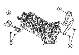
|
Slinger bolts (C) |
: 32.9 N┬Ęm (3.4 kg-m, 24 ft-lb) |
For M/T models, separate the engine
and transaxle assembly using the following procedure: Install engine slinger to front
cover front left side (A) and cylinder head rear right side (B).
|
Slinger bolts (C) |
: 32.9 N┬Ęm (3.4 kg-m, 24 ft-lb) |
INSTALLATION
Installation is in the reverse order of removal.
CAUTION:
-
Do not allow engine oil to get on engine mounting insulator. Be careful not to damage engine mounting insulator.
-
Check that each engine mounting insulator is seated properly, and tighten nuts and bolts.
-
After installation of engine and transaxle assembly, refer to Inspection.
-
Refill engine coolant. Refer to Refilling.
-
For M/T models, refill clutch fluid. Refer to Refilling.
-
When installing the drive shaft (RH/LH), note the following:
-
Install new circular clip on drive shaft in circular clip groove on transaxle side.
CAUTION:
-
Do not reuse circular clip.
-
Make sure new circular clip on drive shaft is securely fastened and engaged into groove.
-
-
In order to prevent damage to differential side oil seal, place Tool (A) onto oil seal before inserting drive shaft as shown. Slide drive shaft into slide joint and tap with a suitable tool to install securely.
Warning:
Ensure that the circular clip is properly engaged, otherwise the joint sub-assembly could pull away from transaxle during Nissan Sentra vehicle operation resulting in loss of drive force and possible drive shaft damage, which may cause a crash and serious injury or damage the drive shaft.
Tool
: KV38107900 (NI-52469-1)
-
To ensure the circular clip is properly engaged, pull the joint sub-assembly (1) in the axial direction away from the transaxle assembly (
 ) while listening for clicking sounds.
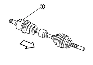
-
Clean the mating surfaces of the wheel hub lock nut and the wheel hub and bearing.
CAUTION:
Do not apply lubricating oil to these mating surfaces.
-
Apply a moderate coat of paste [service parts (440037S000)] to bearing surface (A) as shown.
 Note:
Note:
Always check with the Parts Department for the latest parts information.
-
Hold the wheel hub and bearing using suitable tool. Tighten the wheel hub lock nut.
Wheel hub lock nut
: 165 N┬Ęm (17 kg-m, 122 ft-lb)
CAUTION:
-
Do not reuse the wheel hub lock nut.
-
Since the drive shaft is assembled by press-fitting, use a torque wrench to tighten the wheel hub lock nut. Do not use a power tool.
-
Too much torque causes axle noise. Too little torque causes wheel bearing looseness. Tighten the wheel hub lock nut to the specification.
Tool number
: KV40104000 (ŌĆāŌĆöŌĆā)
-
-
Using hammer (A) and cold chisel (B) stake the wheel hub lock nut (C) as shown.
Warning:
To avoid the risk of death or severe personal injury:
-
Use the following range when staking the wheel hub lock nut.
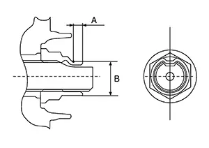
(A)
: 6.2 mm (0.244 in)
(B)
: 26.4 - 27.8 mm (1.039 - 1.094 in)
-
-
Inspection
Inspection
INSPECTION AFTER INSTALLATION
Check wheel alignment. Refer to Inspection.
Adjust the neutral position of the steering angle sensor. Refer to Description.
Inspection for Leakage
The following are procedures for checking fluids leakage, lubricates leakage, and exhaust gases leakage.
-
Before starting engine, check oil/fluid levels including engine coolant and engine oil. If less than required quantity, fill to the specified level. Refer to Fluids and Lubricants.
-
Use procedure below to check for fuel leakage.
-
Place ignition switch in the ŌĆ£ONŌĆØ position (with engine stopped). With fuel pressure applied to fuel piping, check for fuel leakage at connection points.
-
Start engine. With engine speed increased, check again for fuel leakage at connection points.
-
-
Run engine to check for unusual noise and vibration.
Note:
If hydraulic pressure inside timing chain tensioner drops after removal/installation, slack in guide may generate a pounding noise during and just after the engine start. However, this does not indicate an unusualness. Noise will stop after hydraulic pressure rises.
-
Warm up engine thoroughly to check there is no leakage of fuel, or any oil/fluids including engine oil and engine coolant.
-
Bleed air from lines and hoses of applicable lines, such as in cooling system.
-
After cooling down engine, again check oil/fluid levels including engine oil and engine coolant. Refill to the specified level, if necessary.
Summary of the inspection items: Items
Before starting engine
Engine running
After engine stopped
Engine coolant
Level
Leakage
Level
Engine oil
Level
Leakage
Level
Transmission / transaxle fluid
AT & CVT Models
Leakage
Level / Leakage
Leakage
MT Models
Level / Leakage
Leakage
Level / Leakage
Other oils and fluids*
Level
Leakage
Level
Fuel
Leakage
Leakage
Leakage
Exhaust gases
ŌĆö
Leakage
ŌĆö
*: Power steering fluid, brake fluid, etc.
Other materials:
Trunk Lid Opener Actuator
Component Function Check
Component Function Check
CHECK FUNCTION
CONSULT
Select "Trunk/back door" in "Active Test" mode of
"BCM(TRUNK)".
Select ŌĆ£OnŌĆØ to check tha ...
M/t Oil
Inspection
Inspection
OIL LEAKAGE
Make sure that gear oil is not leaking from
transaxle or around it.
OIL LEVEL
Remove
filler plug (1) and gasket from transaxle case.
Check the
oil level from filler plug mounting hole as shown.
CAUTION:
Do not start engine whi ...
C1601-16 Battery Power Supply
Dtc Description
DTC Description
DTC DETECTION LOGIC
DTC No.
CONSULT screen terms
(Trouble diagnosis content)
DTC detection condition
...