Nissan Sentra Service Manual: Unit removal and installation
TRANSAXLE ASSEMBLY
Exploded View
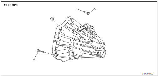
- Transaxle assembly
 Refer to INSTALLATION
Removal and Installation
WARNING:
Do not remove the radiator cap when the engine is hot. Serious burns could occur from high pressure coolant escaping from the radiator. Wrap a thick cloth around the cap. Slowly turn it a quarter turn to allow built-up pressure to escape. Carefully remove the cap by turning it all the way.
CAUTION:
Do not reuse CSC (Concentric Slave Cylinder). The CSC slides back to the original position every time the transaxle assembly is removed. This action may allow dust or contaminants to gather on the sliding parts and damage a seal of CSC causing clutch fluid leakage.
NOTE:
When removing components such as hoses, tubes/lines, etc., cap or plug openings to prevent fluid from spilling.
REMOVAL
- Remove the engine and transaxle assembly. Refer to EM-82, "M/T : Removal and Installation".
- Disconnect the reverse lamp switch harness connector.
- Remove the bolts that fasten the transaxle assembly and engine assembly.
- Remove transaxle assembly from the engine assembly.
- Remove engine mounting bracket (LH). Refer to EM-82, "M/T : Exploded View".
- Remove CSC. Refer to CL-16, "Removal and Installation".
INSTALLATION
Installation is in the reverse order of removal.
CAUTION:
- When replacing an engine or transaxle you must make sure any dowels are installed correctly during re-assembly
- The transaxle assembly must not interfere with the wire harnesses and clutch tube.
- Improper alignment caused by missing dowels may cause vibration, oil leaks or breakage of drive train components.
- When installing transaxle assembly, do not bring input shaft into contact with clutch cover.
- Tapping work for tapping bolts is not applied to new transaxle case. Do not perform tapping by other than screwing tapping bolts because tapping is formed by screwing tapping bolts into transaxle case.
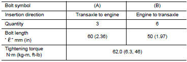
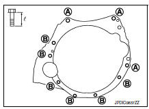
Tighten transaxle assembly mounting bolts to the specified torque. As shown viewing from the engine.
Inspection
INSPECTION AFTER INSTALLATION
- Check the operation of the control linkage. Refer to TM-26, "Inspection".
- Check the oil level and for oil leaks. Refer to TM-19, "Inspection".
 Removal and installation
SIDE OIL SEAL
Removal and Installation
REMOVAL
Remove front drive shafts. Refer to FAX-18, "6M/T : Removal and
Installation (LH)".
Remove differential side oil seals (1) from clu ...
 Unit disassembly and assembly
TRANSAXLE ASSEMBLY
Exploded View
CASE AND HOUSING
Filler plug
Gasket
Transaxle case
Bushing
Snap ring
Oil channel
Oil gutter
Position switch
Bracket
Differential side oil s ...
Other materials:
P0460 Fuel level sensor
DTC Logic
DTC DETECTION LOGIC
NOTE:
If DTC P0460 is displayed with DTC UXXXX, first perform the trouble
diagnosis for DTC UXXXX.
If DTC P0460 is displayed with DTC P0607, first perform the trouble
diagnosis for DTC P0607. Refer
to EC-350, "DTC Logic".
When the vehicle is ...
Engine protection control at low engine
oil pressure
ENGINE PROTECTION CONTROL AT LOW ENGINE OIL PRESSURE : System Description
SYSTEM DIAGRAM
INPUT/OUTPUT SIGNAL CHART
Sensor
Input signal to ECM
ECM function
Actuator
Engine oil pressure sensor
Engine oil pressure
Engine protection control
Oil pressure warning ...
System description
Component parts
Component parts location
Front tweeter LH
Steering switches
Audio unit
Front tweeter RH
Microphone
Front door speaker LH
Front door speaker RH
Rear door speaker LH
Rear door speaker RH
Rear woofer RH
Rear woofer LH
Antenna amp.
Satellite antenna
Win ...
