Nissan Sentra Service Manual: Dtc/circuit diagnosis
Eco mode switch
Component function check
1. Check eco mode switch operation
- Turn ignition switch on.
- Check ECO mode indicator lamp turns ON/OFF on combination meter when turn ECO mode switch ON/ OFF.
Is the inspection result normal? YES >> GO TO 2.
NO >> Proceed to DMS-16, "Diagnosis Procedure".
2. Check eco mode switch illumination function
- Turn on the headlamp.
- Check eco mode switch illumination lights up.
Is the inspection result normal? Yes >> inspection end
No >> proceed to dms-16, "diagnosis procedure".
Diagnosis procedure
Regarding Wiring Diagram information, refer to DMS-8, "Wiring Diagram".
1.Check eco mode switch illumination function
- Turn ignition switch ON.
- Turn on the headlamp.
- Check that the eco mode switch illumination lights up.
Is the inspection result normal? Yes >> go to 7.
No >> go to 2.
2.Check eco mode switch illumination power supply-1
- Turn off the headlamp.
- Turn ignition switch off.
- Disconnect eco mode switch harness connector.
- Turn ignition switch ON.
- Turn on the headlamp.
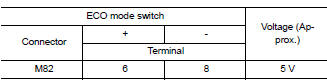
- Check the voltage between eco mode switch harness connector terminals.
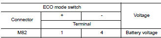
Is the inspection result normal? Yes >> check intermittent incident. Refer to gi-39, "intermittent incident". If ok, replace eco mode switch. Refer to dms-21, "removal and installation".
No >> go to 3.
3.Check eco mode switch illumination power supply-2
Check the voltage between eco mode switch harness connector and ground.
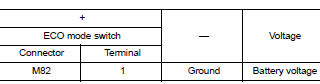
Is the inspection result normal? Yes >> go to 6.
No >> go to 4.
4.Check fuse
- Turn off the headlamp.
- Turn ignition switch off.
- Pull out #37 fuse. Refer to pg-47, "terminal arrangement".
- Check that the fuse is not fusing.
Is the inspection result normal? Yes >> go to 5.
No >> replace the fuse after repair the applicable circuit.
5.Check eco mode switch illumination power supply circuit
- Disconnect ipdm e/r harness connector e45. Refer to inl-26, "wiring diagram".
- Check the continuity between ipdm e/r harness connector and eco mode switch harness connector.
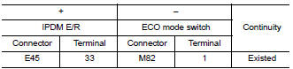
- Also check harness for short to ground.
Is the inspection result normal? Yes >> perform ipdm e/r auto active test and check tail lamp relay operation. Refer to pcs-9, "diagnosis description" (with intelligent key), pcs-37, "diagnosis description" (without intelligent key).
No >> repair or replace error-detected parts.
6.Check ground circuit
- Turn off the headlamp.
- Turn ignition switch off.
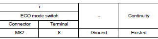
- Check continuity between ECO mode switch harness connector terminal and ground.
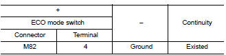
Is the inspection result normal? YES >> Check intermittent incident. Refer to GI-39, "Intermittent Incident".
NO >> Repair or replace error-detected parts.
7.Check eco mode switch circuit
- Turn off the headlamp.
- Turn ignition switch off.
- Disconnect ECO mode switch harness connector.
- Turn ignition switch on.
- Check voltage between ECO mode switch harness connector terminals.
Is the inspection result normal? YES >> GO TO 11.
NO >> GO TO 8.
8.Check ground circuit
- Turn ignition switch off.
- Check the continuity between ECO mode switch harness connector and ground.
Is the inspection result normal? YES >> GO TO 9.
NO >> Repair or replace damaged parts.
9.Check circuit between combination meter and eco mode switch-1
- Disconnect combination meter harness connector m38.
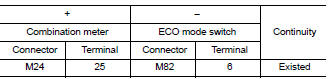
- Check continuity between combination meter harness connector terminal and ECO mode switch harness connector terminal.
- Also check harness for short to power and short to ground.
Is the inspection result normal? Yes >> go to 10.
No >> repair or replace damaged parts.
10.Check combination meter input/output signal
- Connect all of disconnected connectors.
- Check input/output signal of combination meter. Refer to mwi-20, "reference value".
Is the inspection result normal? Yes >> check intermittent incident. Refer to gi-39, "intermittent incident".
No >> repair or replace error detected parts.
11.Check eco mode switch
Check eco mode switch. Refer to dms-18, "component inspection".
Is the inspection result normal? Yes >> check intermittent incident. Refer to gi-39, "intermittent incident".
No >> replace eco mode switch. Refer to dms-21, "removal and installation".
Component inspection
1.Check eco mode switch
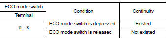
Check continuity between ECO mode switch connector terminals.
Is the inspection result normal? Yes >> inspection end
No >> replace eco mode switch. Refer to dms-21, "removal and installation".
Eco mode
Component function check
1. Check eco mode operation
- Turn ignition switch on.
- Check eco mode indicator lamp turns on/off on combination meter when turn eco mode switch on/ off.
Is the inspection result normal? Yes >> inspection end.
No >> proceed to dms-20, "diagnosis procedure".
Diagnosis procedure
1.Check dtc in ecm
 With consult
Check “Self Diagnostic Results” in “ENGINE”.
Are any DTC detected? YES >> Check DTC detected item. Refer to EC-94, "DTC Index".
NO >> GO TO 2.
2.Check dtc in combination meter
 With consult
Check “self diagnostic results” in “meter/m&a”.
Is any dtc detected? Yes >> check dtc detected item. Refer to mwi-26, "dtc index".
No >> go to 3.
3.Check combination meter
 With consult
- Select “Data Monitor” in “METER/M&A”.
- Check that “eco mode ind” turns on/off when eco mode switch is operated. Refer to mwi-20, "reference value".
Is the inspection result normal? YES >> Replace combination meter. Refer to MWI-77, "Removal and Installation".
NO >> GO TO 4.
4.Check eco mode switch system
Check eco mode switch system. Refer to dms-16, "component function check".
Is the inspection result normal? Yes >> inspection end
No >> repair or replace error-detected parts.
 Basic inspection
Diagnosis and repair work flow
Work flow
Overall sequence
Detailed flow
1.Get information for symptom
Get the detailed information from the customer about the symptom (the
condition and the ...
 Removal and installation
Eco mode switch
Removal and Installation
Removal
Remove instrument lower panel LH. Refer to IP-21, "Removal and
Installation".
Remove eco mode switch.
Installation
Installatio ...
Other materials:
Engine assembly CVT
CVT : Exploded View
Washer
Upper torque rod (RH)
Engine mounting insulator (RH)
Engine mounting insulator (LH)
Rear torque rod bracket
Rear torque rod
CVT : Removal and Installation
WARNING:
Situate the vehicle on a flat and solid surface.
Place chocks at front and back o ...
Front wiper arm
Exploded View
Wiper blade (RH)
Wiper arm (RH)
Wiper drive assembly
Wiper arm (LH)
Wiper blade (LH)
Removal and Installation
REMOVAL
Remove the wiper arm cap.
Remove the wiper arm nut.
Raise the wiper arm, then remove the wiper arm.
INSTALLATION
Clean the wiper arm ...
B1429 Seat belt buckle switch RH
Description
DTC B1429 SEAT BELT BUCKLE SWITCH RH
The air bag diagnosis sensor unit monitors the seat belt buckle switch RH
status. If the control unit detects an
open or short condition in the circuit, it will set the DTC.
PART LOCATION
Refer to SRC-5, "Component Parts Location".
D ...
